-
Xinzhen Town Industrial Zone, Wen'an County, Langfang City, Hebei Province

What Is a Cable Tray? Types, Uses & Selection Guide
Recent News
View Products
Contact Us
Table of Contents
Introduction

A cable tray is easy to recognize but surprisingly easy to specify incorrectly. At first glance, it appears to be a straightforward structure for carrying cables. In a real electrical or industrial installation, however, its job is broader: it has to support cable weight, maintain an organized route, work with bends and fittings, fit within limited structural space, tolerate the surrounding environment, and remain accessible when the system changes.
That is why choosing a cable tray should not begin with appearance or width alone. The better starting point is the cable system itself. Cable type, quantity, outside diameter, weight, routing direction, separation requirements, bend radius, environmental exposure, support spacing, and future expansion all influence the final tray configuration.
A well-designed cable tray system can make installation easier and improve cable visibility, inspection, modification, and maintenance. A poorly matched system may still hold the cables initially, but problems can emerge later through overcrowding, excessive loading, difficult access, corrosion, unsuitable fittings, or poorly planned support locations.
This guide explains what a cable tray is, how different tray structures work, how materials affect performance, and which practical factors should guide selection for industrial, electrical, communication, automation, and infrastructure cable routing.
What Is a Cable Tray?
A cable tray is a structural system designed to support and route insulated electrical, control, communication, instrumentation, and other suitable cables along an organized path.
The general concept of a cable tray includes the tray sections themselves together with the fittings and supporting components required to create a continuous cable route. Cable trays are available in several structural forms, including ladder, ventilated or perforated, solid-bottom, and wire-mesh configurations.
Unlike a pipe-like cable routing method in which cables are pulled through an enclosed pathway, many cable tray structures keep the cables relatively accessible. This is useful where inspection, additional cable installation, reorganization, or replacement may be required during the operating life of a facility.
The tray should not be considered a storage shelf for cables. It is part of an engineered support system. Its side rails, base or rungs, joints, bends, reducers, brackets, hangers, connectors, and structural attachments all contribute to the way loads are transferred into the surrounding structure.
This system perspective is one of the most important concepts in cable tray design. A strong tray section cannot compensate for an unsuitable bracket, excessive support span, overloaded connection, or poorly designed change in direction.
How Does a Cable Tray System Work?
Cable weight enters the tray through the surface that directly supports the cables. In a ladder tray, that load is transferred through the rungs into the side rails. In a perforated or solid-bottom tray, the bottom surface helps distribute cable weight toward the side structure. Wire-mesh designs distribute the load through their welded grid.
The tray then transfers this load into brackets, crossbeams, trapeze supports, hangers, frames, or other structural supports. Those supports ultimately transfer the load into the building, equipment structure, or other approved mounting surface.
This explains why tray dimensions cannot be separated from support design.
Imagine two identical cable trays carrying the same cable bundle. One is supported at relatively short, correctly designed intervals, while the other has much larger unsupported spans. Although the tray material and width are identical, their structural behavior can be significantly different.
Changes in direction make the system more complex. Horizontal bends, vertical bends, tees, crosses, reducers, and risers alter both the cable path and the structural arrangement. Cable weight may also become concentrated around transitions or vertical sections.
For practical design, it is therefore more useful to think about the entire route than to evaluate individual straight tray sections independently.
Main Types of Cable Tray
Different cable tray structures exist because cable routes do not all have the same requirements. Cable size, load, ventilation, physical protection, maintenance frequency, routing flexibility, and surrounding conditions can favor different configurations.
Aoyunte’s current cable tray product range includes multiple tray configurations designed for different cable-management conditions rather than treating cable tray as one single structure.
The most appropriate type should therefore be selected according to the actual cable route.
| Cable tray type | Structural feature | Main design consideration | Typical advantage |
|---|---|---|---|
| Ladder cable tray | Side rails connected by transverse rungs | Cable weight, rung spacing and support span | Open structure and easy cable access |
| Perforated cable tray | Bottom surface with ventilation openings | Cable arrangement, airflow and bottom support | Broad cable support with ventilation |
| Solid-bottom cable tray | Continuous bottom surface | Heat, protection and internal cable layout | Continuous support and greater separation |
| Wire-mesh cable tray | Welded open-grid structure | Cable bundle weight and support interval | Flexible routing and high accessibility |
| Low-voltage cable tray | Designed around smaller signal, data or control cables | Separation, organization and route flexibility | Organized routing for lower-load cable systems |
A ladder cable tray is often suitable for routes carrying larger cables where ventilation and accessibility are important. The transverse rungs support the cables at intervals while leaving much of the cable surface exposed.
A perforated cable tray provides a more continuous supporting surface. The openings allow some air circulation while the base gives smaller cables broader support.
A solid-bottom tray provides continuous support beneath the cable bundle. Its more enclosed structure can be useful where physical separation from the surrounding environment is important, although thermal conditions should be considered because airflow differs from an open tray.
Wire-mesh systems are highly open and can be convenient where routes contain many smaller cables or frequent changes. Their mechanical behavior should still be evaluated according to load and support conditions rather than assuming that all open tray designs perform similarly.
The important point is not to identify which type is universally “best.” Each design solves a different combination of cable-support problems.
Cable Tray Materials and Surface Protection

Cable tray material determines far more than appearance. It influences structural weight, corrosion behavior, installation handling, electrical characteristics, compatibility with the surrounding environment, and long-term maintenance requirements.
Steel is widely used where structural strength is a major consideration. Different protective surface treatments can be applied depending on exposure conditions.
Stainless steel can be considered where resistance to corrosion or demanding environmental exposure is especially important. The surrounding chemicals, moisture, cleaning processes, temperature, and atmospheric conditions should be reviewed rather than selecting the material simply because it is generally associated with corrosion resistance.
Aluminum offers a different balance between structural performance and weight. Its relatively low density can reduce the dead load imposed on supporting structures and may simplify handling during installation.
Fiberglass-reinforced or other composite cable tray systems provide non-metallic alternatives for environments where corrosion resistance, electrical insulation characteristics, or reduced metallic content are important. Their structural behavior differs from metallic systems, so support intervals and load assumptions should follow the specific product design.
Surface protection should also be considered as part of the material system rather than as a decorative finish. If coated or galvanized components are cut, drilled, damaged, or modified during installation, the resulting exposed areas may require appropriate treatment according to the manufacturer’s installation requirements.
The correct material is therefore the one that performs appropriately in the actual operating environment while meeting structural and installation requirements.
How to Select the Right Cable Tray
Cable tray selection should begin with the cable schedule.
Before choosing a tray, identify which cables must use the route, their approximate outside diameters, their weight per unit length, how they need to be grouped, and whether future circuits are expected.
This information provides the basis for determining usable width and structural load. It also helps identify whether the cables need continuous bottom support, periodic rung support, separation, additional fastening, or special bend geometry.
The next step is to understand the route itself.
A long straight corridor creates different demands from a route containing multiple bends, elevation changes, equipment connections, or branch points. Available structural support locations can also affect the most practical tray design.
The environment should then be evaluated. Moisture, contaminants, corrosive substances, temperature variation, dust, vibration, exposure to mechanical impact, and cleaning methods can influence material and surface selection.
Finally, maintenance should be considered before the tray is installed rather than afterward.
If cables will regularly be added or reorganized, access may be particularly important. If the route will become difficult to reach after construction is completed, inspection and durability may deserve greater emphasis.
A practical cable tray decision therefore combines four questions: what must the tray carry, where must it travel, what conditions will it experience, and how will the system be maintained later?
This approach produces a more reliable specification than selecting a tray from dimensions alone.
Cable Tray Width, Height and Load Capacity
Cable tray dimensions determine whether cables can be arranged correctly, but physical capacity and structural capacity are not the same thing.
Width describes the lateral space available for cables. A wider tray can accommodate a broader cable arrangement, but it can also allow more cable weight to be installed. Increasing width without reviewing structural loading can therefore create a mismatch between available space and actual load capacity.
Height or side-rail depth affects cable containment and, depending on tray design, can also influence structural behavior. Higher sides may accommodate deeper cable groups, but excessive stacking is not automatically desirable. Lower cables can become difficult to inspect, replace, or reorganize when several layers accumulate above them.
The number of cables should not be used as the primary sizing method. Ten small cables may occupy less space and create less weight than two large cables. Cable diameter, weight, flexibility, grouping, and arrangement are more meaningful than cable count.
The practical layout also matters. Round cables do not perfectly fill a rectangular tray. Real installations contain gaps between cables, restraints, dividers, connectors, and space required for technicians to position or remove cables.
Load capacity must then be evaluated separately. Tray material, profile, thickness, rung or bottom structure, joints, support spacing, and concentrated loading all affect structural performance.
This distinction helps avoid a common error: assuming that because cables physically fit inside a tray, the tray can necessarily support them under the planned span conditions.
Why Support Spacing Is Part of Cable Tray Selection
Support spacing is sometimes treated as an installation decision made after the tray has already been selected. In reality, it should influence tray selection from the beginning.
As unsupported distance increases, structural demand on the tray changes. The exact relationship depends on tray material, side-rail geometry, cross-section, joints, cable load, fitting position, and support arrangement.
The surrounding building or equipment structure may also limit where supports can be installed. A route drawn across an open area may look simple on a layout, but if suitable structural attachment points are widely spaced, a tray intended for shorter spans may not be appropriate.
Support positioning becomes especially important around fittings. Bends, tees, crosses, reducers, and vertical transitions change the direction of the route and can create different loading conditions from straight sections.
This is why structural planning should happen alongside cable routing. The existing electrical cable tray system guide also discusses the relationship between tray types, installation conditions, support, and industrial cable routing.
A useful project drawing should therefore show more than the tray centerline. It should make the relationship among tray dimensions, fittings, cable routes, structural support locations, and surrounding services clear enough to identify conflicts before installation.
Cable Tray Fittings Matter More Than They Appear
Straight cable tray sections usually receive most of the attention during early design, but fittings often determine whether a route is practical.
Horizontal elbows allow the tray to change direction on the same level. Vertical bends move cables between elevations. Tees and crosses divide or combine routes, while reducers connect tray sections with different widths.
Each fitting occupies physical space beyond the straight tray footprint.
Cable bending requirements are particularly important. A tray may provide enough width along a straight route but still create problems if the bend geometry does not provide sufficient room for the cables to change direction naturally.
Large or relatively stiff cables generally need more space through transitions than small flexible cables. For this reason, checking the most difficult bend or junction early in the layout process can reveal sizing problems that would not be visible from straight-run capacity alone.
Fittings also influence support positions. A complicated junction carrying several cable groups should not automatically be treated like an ordinary straight section.
Accessories, connectors, covers, dividers, support hardware, and fastening systems should be coordinated with the tray material and dimensions so that the completed system functions as one assembly.
Cable Tray vs Conduit: Different Approaches to Cable Routing
Cable tray and conduit can both create organized cable routes, but they approach cable management differently.
A tray supports groups of cables along an accessible route. Many tray configurations leave the cables visible or relatively easy to reach, which can simplify inspection, modification, and future additions.
Conduit encloses cables inside a tube-like pathway. It can provide a high degree of physical separation from the surrounding environment, but modifications may require cables to be pulled through the enclosed route.
This difference makes accessibility an important selection factor.
A cable tray can be especially practical where many cables follow a common route and the system is expected to change. Additional cables can often be introduced into accessible tray sections without rebuilding the entire pathway.
That does not mean cable tray should replace conduit in every situation. Environmental protection, cable type, mechanical exposure, routing density, maintenance expectations, and applicable technical requirements all influence the correct system.
In many installations, the two methods are used together. Cable trays can form the main distribution route while other cable-protection methods handle local connections, equipment entries, or sections requiring different levels of protection.
The useful question is therefore not “Which system is better?” but “Which routing method solves the requirements of this section of the installation?”
Where Cable Tray Systems Are Commonly Used
Cable tray systems are particularly useful where multiple cables need to follow organized routes across a facility or infrastructure system.
Industrial production environments may require power, control, signal, instrumentation, and automation cables to pass between equipment groups. A structured tray route helps keep these cables organized while preserving access for inspection and equipment changes.
Electrical distribution routes can involve larger power cables and heavier loading conditions. Here, tray structure, support span, bend radius, cable weight, and material selection become especially important.
Communication and data systems may involve a much larger number of smaller cables. Accessibility, cable separation, route flexibility, and future additions can become greater priorities than heavy structural loading.
Automation systems frequently combine control, communication, sensor, and power connections. Organized routing can make cable identification and maintenance easier when machinery or process equipment is modified.
Utility corridors and technical spaces also benefit from clear cable routing because multiple services may compete for limited space. Coordinating the tray elevation, width, fittings, and support structure during design can prevent later conflicts.
The application category alone should never determine the cable tray type. Two facilities performing similar functions can have very different cable quantities, environmental conditions, structural limitations, and maintenance strategies.
The actual operating conditions remain more important than the name of the industry.
Common Cable Tray Selection Mistakes
One of the most frequent mistakes is choosing a cable tray according to width alone.
Width answers only one question: how much lateral space the tray offers. It does not confirm whether the tray can support the installed weight, tolerate the environment, fit around bends, or work with the intended support spacing.
Another problem is selecting material before understanding environmental exposure. A familiar material may perform well in many locations but still be unsuitable when moisture, chemicals, temperature, contaminants, or cleaning processes differ from normal conditions.
Support design can also be underestimated. Increasing the distance between supports changes the structural conditions of the tray. A tray that performs correctly under one support arrangement should not automatically be assumed to behave the same way under another.
Future expansion is another area where judgment matters. Leaving some usable capacity can make later cable additions easier, but greatly oversizing a tray without considering structural consequences is not necessarily good design.
More available space can eventually lead to more cable loading. If future additions were not included in the original structural assumptions, the tray may become overloaded even though it still appears to have physical space available.
Fittings are sometimes considered too late. A route that works on straight sections can become impractical around bends, branch connections, or vertical transitions if cable geometry was not considered early enough.
Finally, a cable tray should not be selected only because it resembles a tray used successfully elsewhere. Cable systems that look similar can differ significantly in load, span, cable type, environment, and maintenance requirements.
Installation Quality Affects Cable Tray Performance
Even a correctly specified cable tray can perform poorly if installation changes the assumptions used during design.
Tray sections should remain aligned so that cables do not encounter unnecessary edges or abrupt changes in direction. Joints should use compatible connection methods, and support components should be positioned according to the requirements of the selected system.
Field cutting and drilling deserve attention because they can alter protective surfaces and, depending on location, affect structural details. Modified areas should be treated according to the requirements of the material and protective finish.
Cable installation itself should also be controlled.
Cables should not be forced into bends that are too tight simply because the tray fitting has available space. Heavy cable groups should be distributed according to the intended layout rather than concentrated unexpectedly on one side or in one short section.
Vertical and inclined routes may require additional cable restraint. In these sections, the tray provides the pathway, while suitable fastening prevents the cable weight from creating unwanted movement or stress.
Accessibility should remain after installation. Filling every available opening with cables, supports, or surrounding services may make the original layout compact, but it can also make later inspection and maintenance unnecessarily difficult.
Installation quality is therefore not separate from cable tray design. It is the stage where the assumptions made during design are either preserved or lost.
Cable Tray Maintenance and System Expansion
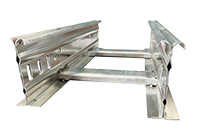
One of the practical advantages of an accessible cable tray is that its condition can often be inspected without dismantling large sections of the routing system.
Routine inspection should look for deformation, damaged supports, loose connections, corrosion, coating damage, displaced cables, debris, abnormal cable concentration, and modifications that were not part of the original layout.
Support points deserve particular attention because they transfer the system load into the surrounding structure.
Cable additions should also trigger a review of the route rather than being treated as unlimited use of remaining physical space.
A tray may still have visible empty width while approaching its intended structural loading. New cables can also alter grouping, thermal conditions, separation, bend congestion, and maintenance access.
Removing abandoned cables can sometimes be more effective than increasing tray capacity. Old cables that remain indefinitely occupy usable space and add weight without contributing to the active system.
For larger changes, adding a parallel route or modifying a branch section may be more practical than replacing every section with a larger tray.
Good lifecycle management therefore involves both physical inspection and accurate knowledge of how the cable route has changed since installation.
Conclusion
A cable tray is more than a metal or composite channel used to keep cables off the floor. It is a structural cable-management system that connects cable requirements with the physical route, supporting structure, environment, fittings, installation method, and future maintenance strategy.
The most suitable tray type depends on what the cables actually need. Ladder systems emphasize open support and accessibility, perforated trays provide broader bottom support with ventilation, solid-bottom designs provide continuous support, and wire-mesh systems offer flexibility for suitable cable groups.
Material, width, height, load capacity, support span, bend geometry, and environmental resistance should then be evaluated as related decisions rather than separate specifications.
When these factors are considered together, a cable tray can remain useful well beyond the initial installation. It provides an organized route that is easier to inspect, modify, maintain, and adapt as the cable system develops over time.
FAQ
What is a cable tray used for?
A cable tray is used to support, organize, and route electrical, control, communication, instrumentation, and other suitable cables. It creates a defined cable pathway while allowing different levels of ventilation, physical support, visibility, and maintenance access depending on the tray structure selected.
What are the main types of cable tray?
Common cable tray structures include ladder, perforated or ventilated, solid-bottom, and wire-mesh designs. Each supports cables differently. The correct type depends on cable size, weight, required ventilation, bottom support, environmental protection, accessibility, support spacing, and route geometry.
How do I choose the right cable tray?
Begin with the cables rather than the tray. Review cable diameter, weight, quantity, grouping, bend requirements, and future additions. Then evaluate tray width, height, material, load capacity, support span, fittings, environmental exposure, installation clearance, and long-term maintenance access.
Is a wider cable tray always better?
No. A wider cable tray provides more routing space but can also accommodate more cable weight and require more installation space. The correct width should match the planned cable arrangement and realistic expansion needs while remaining compatible with tray load capacity, supports, bends, fittings, and available clearance.
How often should a cable tray system be inspected?
Inspection frequency depends on operating conditions, environmental exposure, cable changes, and project requirements. Reviews should focus on supports, joints, corrosion, deformation, cable congestion, damaged surfaces, debris, and newly added loads. Significant cable additions should also prompt a review of system capacity.