-
Xinzhen Town Industrial Zone, Wen'an County, Langfang City, Hebei Province

Ladder Rack Cable Tray for High-Density Cabling: Design That Scales
Recent News
View Products
Contact Us
Table of Contents
Introduction

High-density cable routes rarely stay unchanged for long. New equipment is added, network connections increase, power and control systems expand, and existing cables need to be reorganized without interrupting the surrounding infrastructure. In this environment, the cable pathway has to provide more than basic support.
A ladder rack cable tray creates an open structural route that keeps cables accessible while allowing the system to expand in a controlled way. Its ladder-style construction uses longitudinal rails and regularly spaced cross members to support cables without enclosing them inside a continuous bottom surface.
This open geometry is particularly useful where cable visibility, ventilation, route flexibility, and future modification are important. At the same time, the apparent simplicity of the structure can lead to poor design decisions if tray width, rung spacing, cable load, bends, supports, mounting position, and future capacity are treated separately.
A reliable ladder rack cable tray system begins with the cables and the route they need to follow. The tray dimensions and support structure are then selected around those requirements. This approach produces a pathway that is easier to install today and less difficult to modify several years later.
What Is a Ladder Rack Cable Tray?
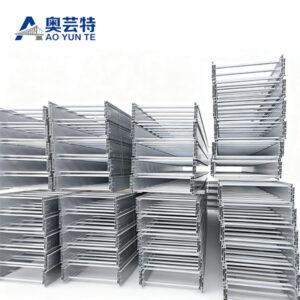
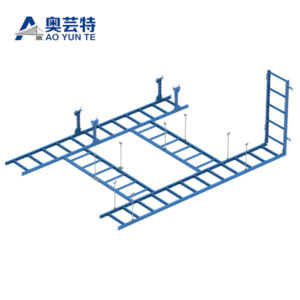
A ladder rack cable tray is an open cable-support structure made from two parallel longitudinal rails connected by transverse rungs or cross members.
The terms ladder rack, cable ladder, and ladder cable tray are sometimes used for closely related cable-management structures, particularly in communication rooms, technical spaces, equipment areas, and overhead cable routes. However, terminology can vary between specifications and applications, so the physical structure and required performance should always be confirmed rather than relying on the product name alone.
Within the broader category of a cable tray, ladder-style systems provide periodic support beneath cables instead of using a continuous base. The spaces between the rungs leave much of the cable surface exposed.
This geometry has several practical consequences.
Cables are easy to see, which makes route tracing and inspection more straightforward. The absence of a solid bottom allows surrounding air to reach more of the cable surface. Technicians can also add or remove cables without opening long enclosed sections.
The same openness means that cable support depends on the relationship between cable properties and rung spacing. A large, relatively stiff cable can behave differently from a small flexible cable placed across the same rung interval.
The ladder rack cable tray should therefore be treated as a structural pathway with defined cable-support conditions rather than simply an open shelf for cables.
Why High-Density Cabling Changes Ladder Rack Design
High-density cabling creates a challenge that cannot be solved simply by selecting a wider tray.
As the number of cables increases, three different types of capacity become important: physical capacity, structural capacity, and operational capacity.
Physical capacity describes whether the cables fit within the usable width of the ladder rack cable tray. Structural capacity describes whether the tray, joints, and supports can safely carry the resulting weight. Operational capacity describes whether technicians can still identify, install, remove, and reorganize those cables after the tray becomes more heavily populated.
These three capacities do not always increase together.
A wider rack creates more physical space, but filling that space also increases cable weight. A deeply packed route may remain structurally acceptable while becoming difficult to maintain. Likewise, a tray can appear to have spare width while fittings or branch points are already congested.
High-density infrastructure therefore benefits from a route-based approach.
Instead of asking only how many cables fit in one straight section, designers should examine how those cables travel through bends, junctions, drops, rack connections, and branch routes. The narrowest or most complicated part of the pathway often determines whether the overall layout remains scalable.
Ladder Rack Cable Tray vs Traditional Ladder Cable Tray
Ladder rack and conventional ladder cable tray often share the same basic visual structure, but their use can place emphasis on different design priorities.
A conventional industrial ladder cable tray may be selected primarily around larger power or control cables, structural load, longer spans, environmental resistance, and heavy-duty supports.
A ladder rack cable tray used around high-density communication or equipment areas may place greater emphasis on cable accessibility, overhead routing, frequent additions and changes, short branch connections, and coordination with equipment rows or rack layouts.
These are not absolute categories. The same structural concept can be adapted to different applications.
Aoyunte’s ladder cable tray range includes multiple materials and structural configurations, demonstrating that ladder-style cable support can be adapted according to load, span, environment, and installation conditions rather than belonging to one single application.
The distinction becomes useful during specification.
If the route carries large and heavy cables across significant structural spans, rail strength and load performance may dominate the design. If the route serves dense communication equipment with frequent cable changes, accessibility, width, cable organization, and mounting position may become equally important.
The correct design follows the actual route rather than the terminology used to describe the tray.
Choosing the Right Width for a Ladder Rack Cable Tray
Width is one of the most visible ladder rack dimensions, but it should be determined from the cable layout rather than from a general preference for more space.
Start with the cable groups expected on the route. Their outside diameters, quantities, functions, grouping requirements, and likely future additions provide the basis for estimating usable width.
The arrangement matters as much as the total cable area.
A group of cables installed in an organized single layer behaves differently from cables stacked repeatedly on top of one another. Heavy layering can reduce visibility and make individual cables more difficult to remove without disturbing nearby connections.
Unused width can therefore have operational value.
It provides room for cable separation, orderly branching, and later modifications. However, this does not mean the largest possible ladder rack cable tray is automatically the best option.
A wider tray occupies more overhead or structural space. Its fittings require more room, and its increased cable capacity can lead to higher loading on hangers and supports.
The practical goal is to create sufficient width for the planned cable arrangement and realistic expansion while keeping the route structurally and spatially efficient.
A well-sized rack should look organized when partially populated and remain manageable when additional cables are introduced.
Rung Spacing and Cable Support
Rung spacing determines how often the cable is physically supported along the route.
This dimension should be considered in relation to the cable rather than treated as a decorative feature of the ladder structure.
Large or relatively rigid cables may bridge wider intervals without significant sagging, while smaller and more flexible cables can require more frequent support. Cable bundles can also behave differently from individual cables because the bundle weight and stiffness change as more cables are added.
Excessive sag between rungs can affect cable organization and place unnecessary mechanical stress on the cable at support points.
Very close rung spacing, on the other hand, increases the amount of structural material without necessarily producing a meaningful improvement for every cable type.
The correct interval therefore balances support, tray structure, cable characteristics, installation practicality, and system requirements.
Cable transitions deserve particular attention.
A cable that is well supported on a straight run may behave differently immediately before a vertical drop or directional change. Additional restraint or support may be necessary around these locations depending on the cable and installation geometry.
Rung spacing should consequently be reviewed together with the complete cable route instead of selected only from the straight rack section.
Material Selection for Ladder Rack Cable Tray
Material selection influences weight, rigidity, corrosion behavior, fabrication, handling, and the support structure required for the completed route.
Steel can provide strong structural characteristics where load and rigidity are major concerns. Surface treatments can be selected according to the environment in which the rack will operate.
Stainless steel provides a different corrosion-resistance profile and can be appropriate where environmental exposure requires stronger material durability.
Aluminum is particularly relevant to overhead cable-management routes because its lower structural weight can simplify handling and reduce dead load on the supporting system. Aoyunte’s aluminum cable ladder is used in cable-management configurations that can be ceiling mounted, wall mounted, positioned above equipment racks, or installed in other organized routing layouts.
Composite materials create another option where non-metallic characteristics or particular corrosion conditions are important.
The material should not be chosen independently from the structural configuration.
A lightweight tray can reduce rack dead weight, but the cable load may still be significant. A highly corrosion-resistant material does not automatically allow longer spans. A strong metal section can still be unsuitable if the surrounding environment attacks its surface protection.
Material, load, support interval, mounting arrangement, and environment therefore need to be evaluated together.
Overhead, Wall and Rack-Top Mounting
One reason ladder rack cable tray systems are useful in dense technical spaces is that they can be positioned away from valuable floor-level working areas.
Overhead mounting creates a clear cable-distribution layer above equipment. Main routes can travel across the space while shorter branches descend toward their destinations.
This arrangement can improve visual organization because cables are separated from equipment bases, walkways, and many other services.
The structural ceiling or overhead support system must still be able to carry the installed load. Cable weight can become substantial as the route expands, so hangers and attachment points should be selected according to the completed system rather than the empty tray.
Wall mounting can be useful around perimeter routes or where overhead structures are not positioned conveniently.
The available wall structure, bracket projection, cable weight, working clearance, and nearby equipment all affect the practicality of this arrangement.
Rack-top mounting places the cable pathway closer to the equipment it serves. This can shorten final cable drops and create direct routing between equipment rows, but the tray should remain coordinated with ventilation, maintenance access, and other services above the racks.
The mounting method should therefore follow the physical architecture of the space. The best location is the one that keeps the cable route accessible without creating structural conflicts or obstructing equipment maintenance.
Main Design Factors for Ladder Rack Cable Tray
A scalable ladder rack cable tray system depends on several factors working together.
| Design factor | What should be evaluated | Why it matters |
|---|---|---|
| Cable quantity | Current cables and expected additions | Determines usable routing capacity |
| Cable diameter | Individual and grouped cable dimensions | Influences tray width and branching space |
| Cable weight | Distributed load along the route | Affects rack and support requirements |
| Rung spacing | Distance between cable support points | Influences cable sag and mechanical support |
| Tray width | Usable lateral cable space | Affects organization and future expansion |
| Support interval | Distance between structural supports | Directly affects structural behavior |
| Bend geometry | Direction changes and cable curvature | Prevents crowded or unsuitable transitions |
| Mounting position | Ceiling, wall, rack-top or other structure | Determines access and load transfer |
| Material | Steel, stainless steel, aluminum or composite | Influences weight and environmental behavior |
| Future changes | Expected cable additions or route modifications | Determines long-term adaptability |
The table illustrates an important principle: no individual dimension defines whether a ladder rack cable tray is suitable.
A wide rack with poor support planning is not a scalable design. A structurally strong rack with inadequate branch capacity can still become difficult to use. A lightweight system that is inaccessible after other services are installed loses much of its maintenance advantage.
The final specification should therefore balance all of these factors rather than maximizing one of them.
Cable Load and Support Spacing

Cable load increases gradually, which can make structural changes easy to overlook.
An empty ladder rack cable tray may be relatively light. Once populated with large numbers of cables, connectors, branch sections, and other approved system components, the load transferred into the supports can change substantially.
Future additions make this particularly important.
Each new cable uses both physical space and structural capacity. A route that still appears only partly filled can therefore be closer to its intended loading condition than visual inspection suggests.
Support spacing affects how the rack responds to this load.
Increasing the distance between supports generally increases structural demand on the longitudinal rails. The exact behavior depends on material, rail profile, section geometry, joints, rack width, cable distribution, and the location of branch fittings.
This is why an allowable support interval should not be copied from an unrelated ladder rack configuration.
The actual tray model and installation arrangement need to be reviewed together.
Cable distribution across the width also matters. Concentrating a large cable bundle along one side can create a different condition from distributing the load more evenly.
The objective is not merely to prevent obvious structural failure. A well-supported route should also remain aligned and serviceable so that cable additions and maintenance do not become more difficult over time.
Managing Cable Density Without Creating Congestion
Cable density and cable organization are not the same thing.
A ladder rack can carry a high number of cables while remaining orderly if cable groups are planned according to destination and function. A much less populated rack can become difficult to manage if cables cross repeatedly, change direction without organization, or accumulate in large service loops.
Branch planning is therefore critical.
Cables that will eventually leave the main route should be positioned so they can reach their branch without passing unnecessarily over other groups.
This becomes especially important where the ladder rack serves multiple equipment rows or technical zones.
Service loops also need control. Extra cable length can be useful for future maintenance, but uncontrolled loops consume routing space and can make surrounding cables difficult to identify.
The objective should be purposeful slack rather than simply storing excess cable wherever open tray space remains.
Cable restraints can help preserve organization where required, but excessive fastening can make later modifications unnecessarily difficult.
A scalable route keeps cables stable enough to remain organized while still allowing technicians to introduce, trace, and remove cables without dismantling large sections of the system.
Bends, Tees and Direction Changes
Straight ladder rack sections usually provide generous access. Direction changes are more likely to become the limiting points in a high-density route.
A horizontal bend requires cables to turn while remaining on approximately the same level. The fitting or fabricated route needs enough space to maintain appropriate cable curvature without forcing the bundle into a tight corner.
Vertical transitions move the cables between elevations and can introduce additional mechanical considerations because cable weight acts differently as the route changes direction.
Tees are especially important in scalable systems.
At a tee, part of the cable population continues along the main route while another group leaves toward a secondary pathway. If cable destinations have not been organized in advance, this area can become congested even when the surrounding straight sections remain relatively open.
A useful design practice is to evaluate fitting capacity independently from straight-run capacity.
If the main ladder rack has room for future cables but the primary branch tee does not, the system does not truly have usable expansion capacity.
The same principle applies to cable drops.
A wide overhead pathway has limited value if every route leading from it to the equipment is already crowded.
Scalable design therefore requires spare routing capacity at transitions, not just on long straight sections.
Ladder Rack Cable Tray and Airflow
Open ladder construction is commonly associated with ventilation because there is no continuous bottom surface beneath most of the cable route.
This allows surrounding air to contact more of the cable bundle than it could in a fully enclosed tray.
However, the tray structure alone does not determine cable temperature.
Cable density, electrical loading, ambient temperature, surrounding airflow, cable grouping, installation layers, and nearby equipment all influence thermal conditions.
This is particularly important in high-density routes.
If cables are tightly stacked across several layers, the open space beneath the tray does not guarantee that every cable receives equal airflow.
Maintaining an organized cable arrangement can therefore support both accessibility and more predictable thermal behavior.
The rack itself should also be coordinated with equipment airflow.
An overhead cable pathway should not unintentionally interfere with ventilation paths, equipment exhaust, cooling infrastructure, or maintenance zones.
The benefit of an open ladder rack is strongest when the entire spatial layout supports good airflow rather than simply relying on the tray’s open geometry.
Separating Different Cable Functions
High-density technical environments often contain several cable functions within a relatively small area.
Power, communication, control, sensor, and other cable systems can follow similar physical routes while having different installation requirements.
A ladder rack cable tray should therefore not be treated as one unrestricted space simply because several cable groups can physically fit on it.
Separation requirements should follow the applicable electrical and communication design for the project.
In some layouts, different cable groups can occupy separate areas of a wider pathway. In others, physically separate ladder racks or alternative routing systems may be more appropriate.
Route organization also helps maintenance even where formal separation is not the primary concern.
When cables serving similar destinations or functions are grouped logically, technicians can trace them more easily and can make changes without disturbing unrelated circuits.
This organization should continue through branches and drops.
Separating cable groups on the main route but mixing them heavily at every tee reduces much of the practical benefit.
The ladder rack should therefore reflect the logical organization of the infrastructure, not merely provide physical support.
Planning for Future Expansion
Future capacity is one of the strongest arguments for an open ladder rack cable tray, but expansion must be designed into the entire route.
Simply leaving unused width in a straight section is not enough.
A future cable must travel through every bend, tee, branch, vertical transition, and equipment connection between its origin and destination. If one of those points is already congested, spare capacity elsewhere has limited practical value.
Structural capacity must expand with physical capacity as well.
If future cable additions are expected, their approximate weight should be considered when selecting tray structure and supports. Otherwise, the route can remain physically spacious while gradually exceeding the assumptions used in its structural design.
The most useful expansion allowance is based on realistic infrastructure planning.
An equipment area expected to change frequently may justify more spare routing space than a stable connection zone with little anticipated modification.
Expansion should also consider direction.
A main route may need spare width, while particular branches require greater allowance because future equipment growth is concentrated in those areas.
Designing the ladder rack cable tray around likely change patterns produces a more useful system than applying the same unused percentage everywhere.
Installation Practices That Improve Long-Term Use
A good ladder rack design can still become difficult to maintain if installation quality is poor.
Rack sections should remain aligned so cables travel through smooth, predictable paths. Joints should use compatible connection methods, and supports should maintain the geometry intended by the design.
Sharp edges should not be allowed to contact cable jackets.
Field-cut sections and fabricated direction changes require careful finishing so cable additions can be made without introducing mechanical damage.
Working clearance is another important consideration.
The finished ladder rack occupies only part of the space technicians need during installation. People still need room to place cables onto the rack, reach fasteners, introduce branch cables, and inspect connections.
A tray installed immediately beneath another service may appear spatially efficient but can make future cable additions difficult.
Cable installation should also preserve the intended layout.
Placing cables wherever temporary space is available can gradually destroy the organization established during design.
Installation teams should understand the routing logic so that cable groups remain arranged according to destination and function as the system grows.
The long-term performance of a ladder rack cable tray therefore depends as much on installation discipline as on the rack itself.
Common Ladder Rack Cable Tray Design Mistakes
One frequent mistake is selecting the tray according to cable quantity alone.
Cable count does not describe cable diameter, weight, stiffness, routing destination, or bend requirements. These factors can be more important than the number of individual cables.
Another mistake is assuming that wider always means more future-proof.
Increasing width creates additional routing space, but it also creates the potential for higher cable loads, larger fittings, and greater competition for overhead space.
Ignoring branch congestion is another common problem.
The main route may appear well planned while tees and drops become difficult to use because too many cables change direction in a small area.
Support positions are sometimes determined too late. If the surrounding structure cannot provide suitable attachment points, the intended tray span may need to change.
Material selection can also be disconnected from the environment. The chosen rack needs to match corrosion exposure, structural requirements, mounting conditions, and installation methods rather than simply following a familiar specification.
Finally, designers sometimes optimize the route for initial installation while giving little attention to maintenance access.
A ladder rack cable tray should remain reachable after surrounding equipment and services are installed. Otherwise, one of the major advantages of an open cable pathway is lost.
Inspection and Lifecycle Management

An accessible ladder rack makes inspection relatively straightforward, but the route should still be reviewed systematically.
Supports and joints should be checked for movement, looseness, deformation, or other changes that could affect alignment.
Cable distribution should also be reviewed.
New cables can gradually concentrate on one side of the rack or crowd important branch points. Service loops may grow as circuits are modified, and abandoned cables can remain in place after they are no longer needed.
These changes consume both physical and structural capacity.
Removing inactive cables where appropriate can restore usable space and make active routes easier to identify.
The operating environment can change as well.
New equipment, modified ventilation, structural additions, or changes to nearby services can alter accessibility and loading conditions.
Lifecycle management therefore involves more than inspecting the rack material. It requires comparing the current cable route with the function the pathway was originally designed to perform.
A scalable ladder rack is one that can absorb reasonable changes without losing organization, structural reliability, or maintenance access.
Conclusion
A ladder rack cable tray is most effective when it is designed as an adaptable cable pathway rather than simply an open support structure.
Its ladder geometry provides excellent visibility and accessibility, but those benefits depend on correct width, rung spacing, material, support interval, mounting position, branch design, cable organization, and available working clearance.
High-density cable environments make these relationships particularly important. More physical cable capacity can create more structural load, while more cables can reduce accessibility unless their routing is deliberately organized.
The best design therefore does not maximize tray size. It balances present cable requirements with realistic future expansion and preserves usable capacity throughout straight runs, bends, tees, drops, and equipment connections.
When these factors are coordinated from the beginning, a ladder rack cable tray can remain organized and serviceable even as the infrastructure around it continues to change.
FAQ
What is a ladder rack cable tray used for?
A ladder rack cable tray supports and organizes cables along an open pathway using longitudinal rails and cross rungs. It is particularly useful where cable visibility, ventilation, overhead distribution, frequent additions, and maintenance access are important, including dense communication and technical cable routes.
How do I choose the right ladder rack cable tray width?
Start with cable diameter, quantity, destination, grouping, and expected future additions. Width should provide practical routing space without encouraging uncontrolled loading. Bends, tees, equipment drops, support capacity, installation clearance, and future branch growth should be evaluated together with the straight rack width.
What rung spacing should a ladder rack cable tray use?
There is no universal rung spacing suitable for every cable. The required spacing depends on cable diameter, flexibility, weight, bundle arrangement, tray design, and route geometry. The selected interval should support cables without excessive sag while remaining compatible with the structural design of the rack system.
Can ladder rack cable tray be installed above equipment racks?
Yes, overhead or rack-top routing can create an organized distribution pathway when the supporting structure, cable load, equipment clearance, airflow, and maintenance access are properly considered. The final arrangement should leave enough working room for cable installation and future changes around the equipment.
Is ladder rack cable tray suitable for future cable expansion?
Its open structure can make future additions easier, but usable expansion depends on the whole route. Spare width should also exist through bends, tees, drops, and branch sections, while supports must have sufficient structural capacity for additional cable weight. Expansion should be planned rather than based only on visible empty space.