-
Xinzhen Town Industrial Zone, Wen'an County, Langfang City, Hebei Province

Cable Tray Dimensions: Width, Height & Length Guide
Recent News
View Products
Contact Us
Table of Contents
Introduction
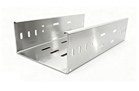
Cable tray dimensions are one of the first factors engineers, contractors, and project planners need to evaluate when designing an electrical cable routing system. A tray that is too narrow can make cable organization difficult, while excessive depth or width may occupy unnecessary installation space and complicate the supporting structure.
However, choosing cable tray dimensions is not simply a matter of selecting a width from a specification table. Width, height, length, material thickness, support span, cable load, bend radius, tray structure, and future cable expansion all affect how the completed system performs.
A cable tray system can use ladder, ventilated, solid-bottom, wire-mesh, and other structural designs. Because these structures support cables differently, two trays with identical nominal dimensions may provide very different usable space, load behavior, ventilation, and maintenance access.
This guide explains how cable tray dimensions are defined, what common dimensional ranges mean, and how to select suitable width, height, and length for industrial, commercial, power, telecommunications, and infrastructure cable routes.
What Are Cable Tray Dimensions?
Cable tray dimensions normally describe several physical characteristics of the tray rather than one single measurement. The most important are width, side height or depth, section length, material thickness, and dimensions associated with fittings or structural components.
When a tray is described as 300 mm wide and 100 mm high, these figures define its nominal geometry. They do not necessarily represent the exact usable space available for cables.
Side walls, dividers, covers, connectors, fasteners, cable restraints, and installation clearance can reduce the effective space inside the system. This is why cable tray dimensions should always be considered together with the intended cable arrangement.
For ladder cable trays, additional dimensions such as rung spacing and rail profile are important. Perforated trays may require consideration of hole patterns and bottom width, while wire-mesh systems have grid dimensions that can influence cable support.
The correct dimensional specification therefore depends on the complete tray structure.
Main Cable Tray Dimensions Explained
The four dimensions most commonly evaluated during cable tray selection are width, height, length, and material thickness.
| Dimension | What It Represents | Main Design Influence |
|---|---|---|
| Width | Horizontal tray space | Cable quantity and arrangement |
| Height | Side-wall or side-rail depth | Containment, structural behavior and cable layering |
| Length | Individual straight tray section | Installation layout and joint positioning |
| Thickness | Thickness of tray material | Strength, weight and structural performance |
| Rung spacing | Distance between ladder rungs | Cable support and sag control |
| Bend radius | Radius of directional fittings | Cable bending and route geometry |
These cable tray dimensions are interconnected. Increasing width, for example, creates additional cable space but can also increase the amount of cable weight carried between supports. Increasing side height may improve containment but also changes the physical envelope needed for installation.
For that reason, dimensions should not be selected independently.
What Is the Standard Cable Tray Width?
There is no single cable tray width that is suitable for every project.
Cable tray dimensions are available across a broad range because cable routes differ considerably. A control wiring route containing small cables may require a relatively narrow tray, while a major power distribution route can require substantially greater width.
Within Aoyunte’s current cable tray range, different structures and materials are designed for industrial, commercial, infrastructure, telecommunications, and other cable management requirements.
Depending on the product configuration, frequently encountered tray widths can include:
| Nominal Width | Typical Sizing Context |
|---|---|
| 50 mm | Small cable routes or limited-space applications |
| 100 mm | Compact cable groups |
| 150 mm | Small to medium cable routes |
| 200 mm | General cable routing |
| 300 mm | Medium cable groups |
| 400 mm | Larger cable routes |
| 500 mm | High cable quantities |
| 600 mm | Larger industrial routing |
| 800 mm and above | High-density or specialized cable routes |
These figures should be treated as dimensional references rather than universal application rules.
The correct width must be determined from cable outside diameters, arrangement, separation requirements, installation method, cable weight, maintenance requirements, and the expected development of the system.
How to Calculate the Required Cable Tray Width

The most reliable starting point is the actual cable schedule.
First identify the cables that will share the route. Record their outside diameters, quantities, cable types, approximate weights, routing requirements, and any required separation between different cable groups.
Next, determine how those cables will physically sit inside the tray.
Simply adding the cross-sectional area of every cable is not always sufficient. Round cables do not fill rectangular space perfectly, and real installations include gaps, cable restraints, dividers, bends, connections, and working space.
A practical width evaluation therefore considers current cable quantity, cable outside diameter, cable grouping, required separation, cable arrangement, installation clearance, maintenance access, and realistic future additions.
For routes where cables need to remain in an organized single layer, the required width can depend strongly on the sum of individual cable diameters and the spacing between groups.
Where layering is permitted, tray height becomes more important, but excessive stacking should not be used simply to reduce tray width. Dense cable bundles can become harder to inspect, identify, remove, and modify.
How Cable Tray Height Affects Selection
Cable tray dimensions also include side height, sometimes referred to as tray depth or side-rail height.
Height influences both cable containment and, depending on the tray design, structural behavior.
Common tray heights can include approximately 50 mm, 75 mm, 100 mm, 150 mm, and 200 mm. Actual availability depends on the particular product structure.
For example, Aoyunte’s current stainless steel cable tray specifications include regular widths from 50 mm to 1200 mm and heights from 50 mm to 200 mm, with configurable section lengths. These figures demonstrate the available dimensional flexibility within one product family rather than defining a universal cable tray standard.
A deeper tray can provide additional containment, but greater depth does not automatically mean cables should be densely stacked.
Designers also need to consider heat dissipation, cable visibility, access from above, divider placement, covers, installation tools, and future cable removal.
Cable Tray Length and Section Design
Length is another important part of cable tray dimensions.
Unlike width and height, tray length usually describes the length of an individual manufactured section rather than the total distance of the cable route.
The selected section length affects joint quantity, support positioning, installation handling, route coordination, structural continuity, and fitting layout.
Longer sections can reduce the number of joints along a straight route, but their handling and structural requirements also need to match the installation environment.
A cable tray route inside an open industrial building may provide very different installation conditions from a crowded mechanical room containing beams, ductwork, piping, equipment, and other services.
The most appropriate section length is therefore determined by both manufacturing configuration and the physical installation environment.
Cable Tray Dimensions by Tray Type
Cable tray dimensions should always be interpreted according to tray type.
Ladder Cable Tray
Ladder trays consist of longitudinal side rails joined by transverse rungs. Width and side-rail height are important, but rung spacing is another critical dimension.
The selected rung spacing should provide appropriate support for the cables being installed. Cable flexibility, diameter and weight can influence how cables behave between adjacent rungs.
For long routes carrying heavier cables, designers must consider width, rail profile, cable load and support span together.
Perforated Cable Tray
Perforated cable trays provide a broader supporting surface beneath the cables while maintaining openings for airflow and drainage.
Useful internal width and height become important because cables rest more continuously on the tray bottom. Perforations, dividers, covers and side structures can also influence usable space.
This type can be useful for routes containing multiple smaller or medium-sized cables that benefit from broader bottom support.
Solid-Bottom Cable Tray
A solid-bottom tray provides continuous support beneath the cables.
Its cable tray dimensions need to account carefully for internal width, side height, cable entry and exit, cover clearance and cable arrangement.
Because the structure is more enclosed than ladder designs, the overall installation environment should also be considered when evaluating airflow and cable density.
Wire Mesh Cable Tray
Wire mesh trays use an open grid structure.
Width and depth remain important, but wire diameter, mesh pattern, support spacing and load characteristics can influence system performance.
Their geometry can provide flexible routing for appropriate communication, control and data cabling applications.
Example Cable Tray Dimension Comparison
The following table demonstrates how nominal cable tray dimensions can be interpreted during preliminary project planning.
| Tray Width | Tray Height | Possible Planning Focus |
|---|---|---|
| 100 mm | 50 mm | Compact cable route |
| 200 mm | 50–100 mm | Small to medium cable groups |
| 300 mm | 50–100 mm | General industrial routing |
| 400 mm | 100–150 mm | Larger cable groups |
| 600 mm | 100–150 mm | High-density routing |
| 800 mm+ | 100–200 mm | Large or specialized cable routes |
This is not a universal cable tray dimension chart for final engineering selection. Different cable types, tray structures, loading conditions, materials, support intervals, local requirements and installation environments can require different configurations.
The table is most useful as a starting point for understanding how width and height work together.
Why Cable Load Matters When Selecting Dimensions
Cable tray dimensions cannot be determined from space alone.
Two cable bundles can require the same tray width while producing very different loads.
A route carrying communication cables may place relatively little structural demand on the tray, while similarly sized space containing large power cables can create a much higher distributed load.
As width increases, additional cable space becomes available. That also means more cable weight could potentially be installed between the same support points.
A wider tray therefore does not automatically solve a sizing problem.
Tray material, structural profile, thickness, side-rail design, connections, support spacing and cable load should be reviewed together.
The objective is not merely to find enough physical space. The complete support system must remain suitable for the installed cables.
How Support Span Changes Cable Tray Selection
Support spacing has a direct relationship with cable tray dimensions and structural performance.
A tray supported at relatively short intervals behaves differently from an identical tray installed across longer spans.
As span increases, the structural demands placed on the side rails and tray body generally become more significant. Tray depth or structural profile may therefore need to change even when the cable quantity stays exactly the same.
This is particularly relevant in factories, warehouses, energy facilities and infrastructure projects where columns or structural beams may determine where brackets or hangers can be installed.
Cable tray selection should therefore include support positions at the same design stage as tray dimensions.
Waiting until installation to determine support spacing can create conflicts between the intended cable tray and the actual building structure.
Dimensions Around Bends, Tees and Fittings
Straight tray width is only part of the required installation space.
Horizontal bends, vertical bends, tees, crosses and reducers can require significantly more room than straight cable tray sections.
Cable bend radius is especially important.
Even when a cable bundle fits comfortably inside a straight tray, the route may become unsuitable if a directional fitting forces cables through a radius that is too tight for the installed cable type.
Designers should review the complete cable route and identify horizontal changes of direction, vertical transitions, tees and branch routes, cross intersections, reducers, cable entry and exit points, and structural obstructions.
This approach prevents a common problem in which the selected cable tray dimensions fit the straight sections but fail to provide sufficient installation space around transitions.
Cable Tray Dimensions and Future Capacity
Future expansion deserves consideration, particularly in industrial plants, data centers, telecommunications facilities and automated production environments where cable routes may change during the operating life of the facility.
However, future capacity should be based on realistic project expectations.
Simply choosing the largest possible cable tray can introduce unnecessary space, structural and installation requirements. On the other hand, designing a tray with no practical expansion capability can make later modifications difficult.
The most appropriate approach is to understand the expected development of the facility.
A fixed process line with limited modification may require a different expansion strategy from a data infrastructure environment where additional cables are likely to be introduced regularly.
Cable tray dimensions should therefore support both current routing requirements and credible future changes.
Material Thickness Is Also a Cable Tray Dimension
Width and height receive most of the attention, but material thickness can also affect tray behavior.
Two trays with the same external dimensions do not necessarily have the same structural characteristics.
Performance can vary according to material, material thickness, side-wall profile, reinforcement geometry, manufacturing process, connection design, support span, and cable load.
This is why cable tray dimensions alone should never be used as a substitute for structural information.
A 300 × 100 mm tray is a geometric description. It does not independently define how much load that specific product can support.
The exact tray configuration should always be evaluated using the structural information applicable to that product and installation.
How Material Choice Affects Cable Tray Dimensions
Steel, galvanized steel, stainless steel, aluminum and FRP cable trays can all be used for cable management, but material selection influences more than corrosion resistance.
Material properties affect weight, stiffness, fabrication, support design, environmental suitability and the structural configuration required for a particular cable load.
A stainless steel system operating in a corrosive industrial area may have the same nominal width as a galvanized tray installed inside a commercial building, but the engineering reasons behind each selection can be completely different.
This is another reason cable tray dimensions should not be evaluated separately from material and environment.
Common Cable Tray Dimension Selection Mistakes
One frequent mistake is selecting width according only to the number of cables. Cable diameter and arrangement usually matter more than cable count alone.
Another is assuming that deeper trays automatically provide better cable capacity. Deep stacking can reduce accessibility and make cable identification and modification more difficult.
Ignoring support span is also problematic. The tray may provide sufficient cable space but still require a different structural configuration for the available support positions.
Designers may also overlook bends and fittings. A route that works perfectly along a straight line can become difficult to install at a tee or vertical transition.
Finally, cable tray dimensions should not be copied directly from another project without reviewing the actual cable schedule, route geometry, structural environment and expected expansion of the new installation.
A Practical Cable Tray Dimension Selection Process
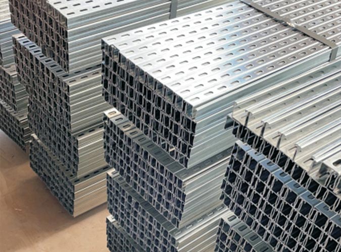
A reliable selection process starts by preparing the cable schedule and identifying cable diameters, quantities, approximate weights and routing groups.
Next, define how the cables need to be arranged and whether separation or dividers are required. Estimate the usable width and height required for the planned cable arrangement, then determine the appropriate tray structure, such as ladder, perforated, solid-bottom or wire mesh.
After that, review cable load together with tray material, thickness, rail structure and available support span. The entire route should also be checked for bends, tees, reducers, vertical transitions and restricted installation areas.
Finally, consider realistic future cable additions and maintenance access before confirming the final cable tray dimensions.
Following this sequence reduces the risk of treating tray sizing as an isolated dimensional decision.
Conclusion
Cable tray dimensions are much more than a width number on a technical drawing. Effective cable tray sizing requires width, height, length, material thickness, tray structure, cable weight, support spacing, bend geometry, installation clearance and future expansion to be evaluated together.
Common dimensional ranges can provide a useful starting point, but there is no single cable tray size suitable for every electrical installation.
The best cable tray dimensions are those that provide sufficient usable cable space while remaining compatible with the structural support system, cable characteristics, installation environment and long-term routing requirements.
For industrial and infrastructure projects in particular, selecting dimensions as part of the complete cable support system provides a more reliable result than choosing tray width first and addressing structural and installation conditions later.
FAQ
What are the most common cable tray dimensions?
Cable tray dimensions normally include width, height, section length and material thickness. Depending on tray type, rung spacing, mesh spacing and fitting radius may also be important. Available dimensions vary between tray structures and manufacturers.
What widths are available for cable trays?
Cable tray widths can range from narrow configurations for compact cable routes to very wide systems for high-density installations. Aoyunte’s current product configurations include widths extending from 50 mm to 1200 mm for several cable tray designs, although the appropriate width should always be determined from project requirements.
How do I determine the correct cable tray width?
Start with cable outside diameters, quantity, arrangement, separation requirements and expected future additions. Then consider usable internal space rather than relying only on nominal outside width.
Does cable tray height affect load capacity?
Height can influence the structural geometry of certain cable tray designs, but height alone does not determine load capacity. Material, thickness, rail profile, tray construction, support span and connection design also affect structural performance.
Are cable tray dimensions standardized?
Common dimensional ranges are widely used, but there is no single dimension suitable for every tray system or project. Final dimensions should match the cable arrangement, tray type, structural requirements, support conditions, environment and applicable project requirements.