-
Xinzhen Town Industrial Zone, Wen'an County, Langfang City, Hebei Province

7 Cable Tray Types Explained: Uses, Differences & Selection
Recent News
View Products
Contact Us
Table of Contents
Introduction

Cable management becomes much easier when the tray structure matches the cables it is expected to support. The difficulty is that cable tray types can look similar in drawings while behaving very differently once they are loaded, supported, connected through fittings, and exposed to real operating conditions.
A ladder tray leaves most of the cable surface open. A perforated tray provides a broader supporting base while retaining ventilation openings. A solid-bottom system offers continuous support, while wire-mesh designs use an open grid that can simplify routing for suitable cable groups. Other configurations are developed around narrower routes, low-voltage cabling, or longer structural spans.
These differences affect more than appearance. They influence cable support, ventilation, load distribution, maintenance access, routing flexibility, environmental protection, support spacing, and the way future cables can be added.
The most effective way to compare cable tray types is therefore not to ask which design is best overall. Instead, ask which structure solves the specific problems created by your cable load, routing geometry, environment, available support points, and maintenance strategy.
This guide examines seven practical cable tray types and explains how their structural differences affect real cable-routing decisions.
What Makes Cable Tray Types Different?
A cable tray is part of a structural cable-support system rather than simply a container for cables. The broader definition of a cable tray includes tray sections and associated fittings that create a continuous route for insulated power, control, and communication cables. Ladder, ventilated, solid-bottom, and wire-mesh structures are among the configurations used for different cable-support conditions.
The main difference between cable tray types is the way the structure contacts and supports the cable.
In a ladder tray, cables rest on transverse rungs. In a perforated tray, cables sit on a ventilated sheet-metal base. A solid-bottom tray provides continuous support, while a wire-mesh tray distributes the cable load through a welded grid.
That structural difference affects several other decisions.
An open structure can provide easier visual access and greater exposure of the cable surface to surrounding air. A more continuous base can provide broader physical support for smaller cables. Greater enclosure can help separate cables from surrounding debris, while a flexible grid system can make field routing easier in appropriate applications.
Tray structure also affects load transfer. Cable weight ultimately has to move through the tray into brackets, hangers, frames, crossbeams, or other supports. The dimensions and material of the tray matter, but so do the distance between supports, connection details, fittings, and cable distribution.
This is why cable tray types should be evaluated as complete systems rather than compared by shape alone.
1. Ladder Cable Tray
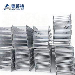
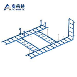
A ladder cable tray uses two longitudinal side rails connected by transverse rungs. The resulting structure resembles a ladder and leaves large open areas between the cable support points.
This configuration is especially useful where cable ventilation, visibility, and access are important. Because much of the cable surface remains exposed, technicians can usually identify cable routes and carry out inspection or modification without removing a continuous tray bottom.
The open structure also reduces the amount of material beneath the cables. However, this does not mean any ladder tray can automatically support heavy cable loads. Structural performance depends on the side-rail profile, material, thickness, rung construction, connection method, cable distribution, and support span.
Rung spacing deserves particular attention. Large cables may be well suited to periodic support, while smaller flexible cables may require a different support arrangement. Cable diameter, mechanical properties, and installation requirements should therefore be considered before deciding that an open ladder structure is appropriate.
Different ladder cable tray configurations can also use aluminum, FRP, coated metal, galvanized construction, and reinforced long-span profiles, showing how one basic tray type can be adapted to significantly different operating conditions.
Ladder systems are particularly relevant when the cable route carries substantial cable groups and requires regular inspection, efficient access, or relatively open cable support.
2. Perforated Cable Tray
A perforated cable tray uses a broader bottom surface containing regularly distributed openings. These openings can vary in shape and arrangement, but the basic design combines continuous or near-continuous cable support with open areas through the tray base.
This creates a different balance from ladder construction.
The bottom provides more direct support beneath smaller cables, while the perforations allow air movement and drainage that would not be available in a completely solid tray. Aoyunte’s current perforated cable tray category uses multiple-hole designs intended to combine cable support with airflow for more complex cable layouts.
Perforated cable tray types can be particularly practical when a route contains several smaller or medium-sized cable groups that benefit from broader base support.
The continuous surface also makes cable organization different from ladder systems. Smaller cables can rest across the base rather than depending entirely on spaced rungs, although the actual cable arrangement still needs to consider load, grouping, temperature, separation, and maintenance access.
Perforations should not be interpreted as evidence that every ventilated tray provides identical thermal performance. Hole area, cable density, tray depth, cover configuration, surrounding airflow, and cable arrangement can all influence actual conditions.
A perforated tray is therefore best understood as a compromise between very open support and continuous-bottom containment.
3. Solid-Bottom and Trough Cable Tray
Solid-bottom cable tray types provide a continuous supporting surface beneath the installed cables.
Compared with ladder or perforated structures, the cables are more physically separated from the area immediately below the tray. This can be useful where continuous support or additional separation from surrounding debris is important. Wikipedia’s cable tray overview likewise distinguishes solid-bottom designs from ventilated and ladder configurations.
The same feature creates a different thermal and maintenance environment.
Because the base contains no large ventilation openings, airflow around the lower part of the cable bundle is different from that in an open ladder structure. Covers can further increase enclosure. Cable density, heat generation, tray depth, ambient temperature, and applicable electrical design requirements therefore need appropriate consideration.
Cable entry and exit also need planning. With an open tray, cables can often enter or leave at more locations. A solid structure can require coordinated fittings or prepared openings to maintain an orderly route.
These cable tray types can be useful where physical containment has greater priority than maximum openness.
However, greater enclosure should not automatically be described as greater overall safety. The correct design depends on the hazard being addressed. Dust, falling objects, mechanical contact, heat dissipation, accessibility, water exposure, and cable maintenance can lead to different conclusions.
The practical question is whether continuous bottom support solves a meaningful requirement of the route.
4. Wire-Mesh Cable Tray
Wire-mesh cable tray uses interconnected metal wires to create an open basket-like support structure.
Its grid construction creates a high degree of openness and makes cables easy to see from multiple directions. The structure can also be practical where routes contain many smaller communication, data, control, or similar cables and where cable changes are expected.
Aoyunte currently places wire-mesh systems within its low-voltage cable tray range and describes the open grid as supporting ventilation, cable visibility, and flexible field routing for appropriate cable groups.
The flexibility of wire mesh should not be confused with unlimited structural capability.
Cable weight, tray width, basket depth, wire diameter, grid geometry, support spacing, fittings, and cable distribution all influence performance. A wire-mesh tray carrying a relatively light cable bundle presents a very different structural condition from the same tray loaded densely with heavier cables.
Field-created changes in direction can be one advantage of this structure, but any modification should preserve the strength and edge condition of the tray.
These cable tray types are especially useful when routing flexibility and cable accessibility are important, provided the cable load and support conditions are appropriate for the selected system.
5. Channel Cable Tray
Channel cable tray uses a narrower supporting structure than many full-width ladder or trough systems.
It can be useful for branch routes, cable drops, localized connections, or routes containing a limited number of suitable cables. Rather than installing a large tray where only a small cable group must travel, a channel configuration can create a more proportionate pathway.
This illustrates an important principle when comparing cable tray types: the main route and branch routes do not necessarily need identical structures.
A large backbone route may require substantial width and structural capacity because many cable groups travel together. As cables leave that route and move toward individual equipment areas, the required pathway can become progressively smaller.
Using an appropriately sized channel can reduce unnecessary structural bulk and simplify routing in restricted areas.
However, the same design factors remain relevant. Cable size, weight, bend radius, support interval, environment, connections, and physical protection must still be evaluated.
A smaller tray does not mean that engineering requirements disappear. In fact, narrow equipment routes can contain tight bends and limited access that make careful planning even more important.
6. Low-Voltage Cable Tray
Low-voltage cable tray describes a cable-management approach developed around communication, data, signal, control, and similar cable networks rather than one single geometric structure.
The category can include mesh, channel, ventilated, and other configurations depending on the cable system.
These routes often create different design priorities from heavy power-cable installations. Cable count may be high while individual cable weight remains relatively low. Route accessibility, organization, separation, bending, identification, and ease of future additions can therefore receive greater attention.
Aoyunte’s low-voltage category specifically covers communication, data, and control cable routing and includes wire-mesh configurations for accessible cable management.
High cable quantity should still not be confused with unlimited tray capacity.
Dense cable bundles can become difficult to identify and maintain even when their combined weight remains within structural limits. Poor organization can also make future modifications unnecessarily disruptive.
Cable separation requirements may influence both tray size and route planning. Power and signal systems should be arranged according to applicable project requirements rather than simply sharing the same tray because unused physical space remains available.
Among cable tray types, low-voltage systems therefore demonstrate particularly clearly that usable capacity is not determined by structural load alone. Accessibility and cable organization are equally important.
7. Long-Span and Reinforced Cable Tray

Long-span cable tray is primarily a structural variation developed for routes where supports cannot be placed as closely as they might be in a conventional installation.
These systems may use deeper side rails, reinforced profiles, modified cross-sections, double-side structures, or other structural features intended to increase stiffness and improve behavior over longer support intervals.
Aoyunte’s current large-span ladder configuration, for example, uses a double-sided beam and ladder-type crossbar structure designed for routes requiring larger spans.
The important point is that “long span” should not be treated as an isolated product label.
Increasing the distance between supports changes the structural condition of the entire tray. Tray self-weight, cable weight, width, material, side-rail geometry, fittings, joints, and load distribution all become relevant.
A wider long-span tray can create a particularly demanding condition because additional width provides room for more cables. If that physical capacity is eventually filled, the load between widely spaced supports may become substantial.
Fittings also need careful coordination because a straight long-span section and a complex tee or bend do not necessarily behave in the same way.
These cable tray types are therefore best selected after the expected support locations have been established. Choosing the tray first and discovering the available structural span later reverses the more reliable design sequence.
Cable Tray Types Comparison
The main cable tray structures can be compared according to the problem they are intended to solve rather than simply by appearance.
| Cable tray type | Cable support style | Ventilation | Access | Key design concern |
|---|---|---|---|---|
| Ladder tray | Spaced transverse rungs | Very open | High | Cable weight, rung spacing and span |
| Perforated tray | Ventilated continuous base | Moderate to high | High | Cable arrangement and bottom support |
| Solid-bottom tray | Continuous closed base | Limited through base | Moderate | Thermal conditions and protection |
| Wire-mesh tray | Open welded grid | Very open | Very high | Cable load and support interval |
| Channel tray | Narrow supporting route | Depends on structure | High | Limited cable quantity and branch routing |
| Low-voltage tray | Varies by configuration | Varies | Usually high | Organization, separation and future changes |
| Long-span tray | Reinforced structural configuration | Depends on tray structure | Depends on design | Load, stiffness and support distance |
This comparison shows why the phrase “cable tray types” covers more than different shapes. Each structure represents a different balance among support, protection, ventilation, accessibility, load capacity, and routing flexibility.
How Material Changes Cable Tray Performance
Tray type describes structural geometry, while material determines another major part of system performance.
Steel can provide high structural rigidity and can be combined with various surface-protection methods. Stainless steel can be considered when corrosion resistance under particular environmental conditions is important. Aluminum reduces structural weight and provides a different combination of corrosion behavior and mechanical characteristics.
FRP and other composite systems add non-metallic characteristics that can be valuable in environments where corrosion resistance or electrical insulation properties are significant.
Material selection should not be separated from cable tray types.
A ladder tray made from aluminum does not have exactly the same structural behavior as an apparently similar ladder tray made from steel or FRP. Likewise, a stainless perforated tray and coated steel perforated tray may share a similar shape while having different environmental and fabrication considerations.
The surrounding conditions should therefore be defined before material selection is finalized.
Moisture, contaminants, chemicals, temperature, outdoor exposure, cleaning processes, structural loading, electrical requirements, and expected service conditions can all influence the decision.
The appropriate material is the one whose properties match both the tray geometry and the operating environment.
How to Choose Between Cable Tray Types
The selection process should begin with the cables rather than with a product catalogue.
First identify the cable groups that must follow the route. Cable outside diameter, weight, flexibility, bend radius, quantity, grouping requirements, and future additions provide the basic information needed to evaluate tray structure.
Next consider the type of support those cables need.
Large cables may be suitable for ladder-style support, while groups of smaller cables may benefit from a more continuous base. Routes requiring strong physical separation from the surrounding environment may justify a solid structure, while frequently changing data or control routes may favor a more accessible configuration.
The route geometry comes next.
A tray running through a long open corridor faces different conditions from one passing through equipment zones with frequent bends, branches, elevation changes, and restricted clearances. The most difficult section of the route can sometimes determine the most practical tray type.
Structural support availability should be evaluated at the same time. If attachment points are widely separated, tray stiffness and span performance become important early in the specification process.
Finally, consider the operating life of the system.
Some cable routes remain almost unchanged after commissioning. Others are modified regularly as equipment, automation, data infrastructure, or electrical distribution changes. A tray that provides good access can have significant practical value where modifications are expected.
Selecting among cable tray types is therefore a process of matching structural characteristics to actual cable and site requirements.
Airflow and Protection Should Be Balanced
Ventilation is often discussed as if more airflow is always better, while enclosure is sometimes presented as if more protection is automatically safer. Neither assumption is sufficient.
Open ladder and wire-mesh cable tray types expose more of the cable surface to surrounding air and make visual inspection easier. This can be valuable for dense cable routes and maintenance access.
Perforated trays create an intermediate condition. They provide broader bottom support while retaining openings that allow air movement through the tray structure.
Solid-bottom systems offer greater separation between cables and the area beneath the tray but reduce direct airflow through the base.
The correct balance depends on the cable and the environment.
A dusty or mechanically exposed location can favor greater physical protection. A cable route where heat management and frequent inspection are major concerns may benefit from a more open design. Some installations may also use covers selectively rather than changing the entire tray structure.
Environmental protection should therefore be defined in terms of the actual hazard. Dust, water, impact, contaminants, falling objects, and temperature do not create identical design requirements.
Once the problem is clearly defined, comparing cable tray types becomes much more meaningful.
Support Spacing and Load Cannot Be Separated from Tray Type
Every cable tray has to transfer its load into a supporting structure.
That load includes the tray itself and the installed cables, together with compatible fittings, accessories, covers where used, and other loads included in the approved design.
Support spacing changes how that load acts on the tray.
As the unsupported distance increases, the structural demand generally becomes more significant. Side-rail geometry, base design, material thickness, joints, fittings, and cable distribution all influence how the tray behaves.
Cable tray types respond differently because their structural sections are different.
A ladder system transfers cable loads through rungs and side rails. A perforated or solid tray uses its base and side structure together. Wire mesh distributes load through a welded grid. Long-span systems may use deeper or reinforced profiles.
This means a load value from one tray design should not be transferred to another simply because their widths are similar.
Cable distribution is equally important. A relatively uniform cable arrangement is different from a route where heavy cables are concentrated on one side or around a fitting.
Support design should therefore develop alongside tray selection rather than after it.
Fittings Can Change Which Cable Tray Type Works Best
Straight tray sections rarely determine every design decision.
Horizontal bends, vertical bends, tees, crosses, reducers, risers, connectors, and transitions are the points where cable routing becomes three-dimensional.
A large cable may fit comfortably along a straight ladder tray but require substantially more space to turn through a bend. A dense group of smaller cables may fit in a perforated tray yet become difficult to organize where several branches meet.
Bending requirements can therefore influence tray type and fitting dimensions.
Accessibility also changes around fittings. A tray that can easily be reached from above along a straight route may pass close to equipment or structural elements at a junction. Installation clearance should account for the space needed to position and secure the cables rather than only the finished tray dimensions.
Reducers can connect routes with different capacities, which means one installation does not always need to use the same tray width or type throughout.
The main route, branch route, equipment connection, and communication section can have different requirements. A coordinated system can therefore use different configurations where appropriate rather than forcing one tray structure into every location.
Common Mistakes When Comparing Cable Tray Types
A common mistake is comparing tray types only by cable capacity.
Physical space is important, but it does not establish structural capacity, ventilation, environmental suitability, accessibility, or fitting requirements.
Another mistake is assuming that an open tray is automatically suitable whenever cooling is important. Thermal performance also depends on cable arrangement, loading, ambient conditions, covers, spacing, and electrical design requirements.
The opposite mistake occurs when a more enclosed tray is selected simply because greater physical protection sounds desirable. Enclosure can change airflow, cable access, drainage, and maintenance conditions, so the actual hazard should be identified first.
Material and structure are also frequently confused.
Stainless steel, aluminum, galvanized steel, and FRP describe materials or material systems. Ladder, perforated, solid-bottom, and wire mesh describe structural configurations. Both choices matter, and one should not be used as a substitute for evaluating the other.
Support conditions can also be overlooked. A tray suitable for one span does not automatically remain suitable when structural attachment points are moved farther apart.
Finally, future expansion should not mean filling every remaining space later. Cable additions change weight, accessibility, grouping, fitting congestion, and sometimes thermal conditions. Expansion should remain part of the system design rather than become uncontrolled accumulation.
Installation and Long-Term Use

Correct tray selection only creates the potential for good performance. Installation determines whether that potential is preserved.
Tray sections should remain aligned, joints should use compatible connection methods, and supports should correspond to the structural assumptions used during selection. Field modifications should not create sharp edges, damaged protective surfaces, or weakened structural details.
Cable placement should follow the intended arrangement rather than simply using whichever area remains open.
Large cable groups should not be concentrated unexpectedly in short sections. Vertical routes may require suitable cable restraint, while bends should maintain appropriate cable curvature.
Maintenance access should remain available after surrounding services are installed.
Over time, cable systems change. New circuits are introduced, old cables are abandoned, equipment is relocated, and communication systems expand. A route that originally had generous capacity can gradually become congested.
Periodic inspection should therefore consider both the tray and the cables. Supports, connections, corrosion, deformation, cable concentration, debris, damaged surfaces, and unauthorized modifications can all affect long-term performance.
The best cable tray types are not simply those that work on the installation date. They are the ones that remain suitable as part of a manageable cable-routing system throughout the expected service life.
Conclusion
Different cable tray types exist because cable-support requirements are fundamentally different.
Ladder trays prioritize open support and accessibility. Perforated trays combine broader bottom support with ventilation. Solid-bottom systems provide continuous support and greater physical separation. Wire-mesh trays emphasize openness and routing flexibility, while channel, low-voltage, and long-span designs address more specific routing or structural conditions.
Choosing between them requires more than identifying the cable quantity. Cable dimensions, weight, support requirements, environmental exposure, route geometry, fittings, ventilation, maintenance access, and future modifications all influence the final decision.
A cable tray performs best when its structure solves a clearly defined cable-management problem. Once the requirements of the route are understood, tray type, material, dimensions, fittings, and support design can be coordinated as one system rather than selected independently.
That approach produces a cable route that is easier to install, inspect, modify, and maintain without relying on one tray configuration for every application.
FAQ
What are the main cable tray types?
Common cable tray types include ladder, perforated, solid-bottom, wire-mesh, and channel configurations, together with systems developed for low-voltage or longer-span routes. Each structure provides a different balance of cable support, ventilation, protection, accessibility, load performance, and routing flexibility.
Which cable tray type is best for large cables?
Ladder trays are often considered for larger cable groups because their rungs provide open structural support and good accessibility. The final choice still depends on cable weight, diameter, rung spacing, tray profile, support span, bends, environmental conditions, and the load rating of the exact tray configuration.
What is the difference between ladder and perforated cable tray?
A ladder tray supports cables on spaced transverse rungs, leaving much of the cable surface open. A perforated tray uses a broader base containing ventilation openings. Ladder designs emphasize openness and access, while perforated designs provide more continuous support for suitable smaller or medium cable groups.
How do I choose between different cable tray types?
Start with cable diameter, weight, quantity, grouping, bend requirements, and likely expansion. Then compare ventilation, bottom support, environmental protection, accessibility, tray material, support span, route geometry, and fittings. The best tray type is the one that satisfies the complete route rather than one requirement alone.
Can different cable tray types be used in one system?
Yes. Main routes, branches, equipment connections, and communication sections can have different cable-support requirements. Compatible fittings and transitions can connect appropriately designed sections where necessary. Each change should still maintain suitable cable support, bend geometry, structural capacity, and installation access.