-
Xinzhen Town Industrial Zone, Wen'an County, Langfang City, Hebei Province

Cable Tray Systems Built for Scalable Power and Data Routing
Recent News
View Products
Contact Us
Table of Contents
Introduction

Cable infrastructure rarely remains exactly as it was on the day a facility begins operation. New equipment is installed, communication networks expand, automation systems become more connected, and additional electrical circuits gradually increase both the quantity and complexity of cabling.
Cable tray systems provide the structural pathway that allows these changes to remain manageable.
A well-designed system does more than support cables between two points. It organizes power, control, communication, instrumentation, and other suitable cable routes while providing the physical capacity, structural support, fittings, and access needed for future modifications.
This makes scalability an important part of cable tray design. Simply selecting a tray with extra width does not create a scalable system. Spare space must also exist through bends, tees, reducers, vertical transitions, equipment drops, and structural supports. The tray must remain accessible, and future cable weight must not exceed the assumptions used in the original design.
The most effective cable tray systems therefore coordinate tray type, dimensions, material, load, support spacing, route geometry, environmental conditions, and future expansion as one design problem. This guide explains how those factors work together and how they influence the long-term performance of modern power and data routing.
What Are Cable Tray Systems?
Cable tray systems are structural pathways used to support and organize insulated electrical, communication, control, instrumentation, and other suitable cables.
The broader cable tray concept includes straight tray sections and the associated components needed to build a continuous route. Depending on the installation, that route can contain ladder sections, perforated trays, solid-bottom structures, wire-mesh trays, elbows, tees, reducers, connectors, brackets, hangers, covers, and other compatible components.
The word “systems” is important because the tray itself is only one part of the cable pathway.
Straight sections carry cables across the main route. Fittings control how cables turn, branch, rise, or descend. Supports transfer the installed load into the surrounding structure, while connectors maintain continuity between individual tray sections.
These elements need to work together.
A wide tray connected through undersized branch fittings can still become congested. A structurally strong tray can perform poorly if supports are spaced incorrectly. A corrosion-resistant tray can lose much of its environmental advantage if its connectors or brackets are unsuitable for the same exposure.
Cable tray systems should therefore be selected and designed as complete routing assemblies rather than as individual products.
Why Scalable Cable Routing Matters
Cable infrastructure often develops in stages.
The first installation may support the immediate requirements of the equipment already in place, but later expansion can introduce additional circuits, communication connections, sensors, monitoring systems, or control devices.
If the original cable pathway was designed only for the initial installation, relatively small additions can create disproportionately large problems.
A tray can become overcrowded even when nearby routes have unused space. Branch fittings can reach capacity before straight sections do. Additional cable weight can increase structural demand, while dense cable layering can make inspection and removal difficult.
Scalability therefore involves more than unused tray area.
A scalable route preserves several forms of capacity at the same time: cable space, structural load capacity, fitting capacity, maintenance access, and practical routing options for future branches.
This is particularly valuable in environments where equipment layouts or digital infrastructure may change during the service life of the facility.
The objective is not to predict every future cable. It is to create enough flexibility that reasonable changes can be incorporated without rebuilding the entire cable management system.
Main Types of Cable Tray Systems
Different cable tray systems provide different forms of cable support, ventilation, accessibility, and physical protection.
The most suitable structure depends on cable size, weight, route geometry, environmental exposure, and maintenance requirements.
| Cable tray system | Structural design | Main advantage | Key selection factor |
|---|---|---|---|
| Ladder tray | Side rails with transverse rungs | Open support and high accessibility | Cable weight, rung spacing and span |
| Perforated tray | Ventilated continuous base | Broader cable support with airflow | Cable arrangement and ventilation |
| Solid-bottom tray | Continuous enclosed base | Greater physical separation | Thermal and drainage conditions |
| Wire-mesh tray | Open welded grid | Flexible routing and visibility | Cable load and support interval |
| Channel tray | Narrow supporting pathway | Efficient smaller branch routing | Cable quantity and route size |
| Long-span tray | Reinforced structural profile | Wider structural support intervals | Load, stiffness and span |
Ladder systems are often considered where larger cable groups benefit from open support. Their rung construction provides regular cable support while leaving much of the route exposed for inspection.
Perforated trays offer a broader supporting surface and retain openings through the bottom. They can suit smaller or medium cable groups requiring greater continuous support.
Solid-bottom systems create a more enclosed pathway. This can provide greater physical separation from the area below the tray, although ventilation, drainage, and cable density require additional consideration.
Wire-mesh trays provide high visibility and flexible routing for suitable lower-load cable groups. Channel systems can be useful where smaller branches do not justify a large full-width tray.
The broader range of cable tray systems demonstrates why tray structure should be matched to the cable route rather than assuming one design is suitable for every section.
Cable Tray Systems for Power Distribution
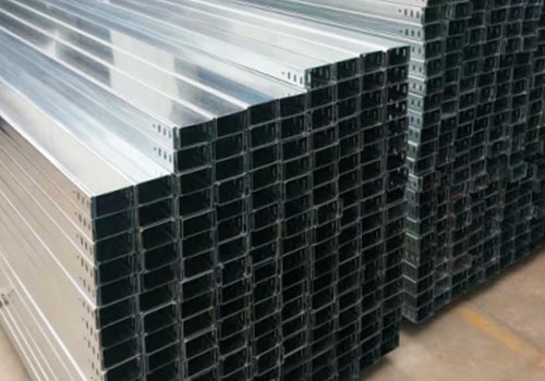
Power cables can create significant structural demands because individual cables may be relatively large and heavy.
The tray needs enough width to arrange the cable group appropriately, but width does not establish structural capacity. A wider tray can simply provide room for more cable weight.
The complete load path must therefore be considered.
Cable weight acts on the tray base or rungs, passes through the side structure, and is eventually transferred into brackets, hangers, frames, or other structural supports.
Cable bending becomes important wherever the route changes direction.
Large power cables can require considerably more space around an elbow or vertical transition than smaller control cables. A straight tray section can therefore have ample capacity while its fittings become difficult to use.
Power routing should consequently be checked as a complete pathway.
The designer should examine not only main straight sections but also bends, branches, risers, equipment entries, and cable drops.
Ventilation can also influence tray selection. Open structures expose more of the cable surface to surrounding air, but actual cable thermal performance still depends on electrical loading, cable grouping, ambient conditions, and applicable design requirements.
Cable Tray Systems for Data and Communication Routing
Data and communication cable routes often present the opposite challenge from large power routes.
Individual cables may be relatively light, but the total cable count can become very high.
This makes organization and accessibility especially important.
A cable tray that is structurally capable of carrying the cables can still become difficult to maintain if cables are layered without clear grouping or routed randomly through branch points.
Main routes should therefore follow a logical structure.
Cables serving similar destinations can be positioned so that they leave the main tray through predictable branches. This reduces crossing around tees and makes cable tracing easier during future changes.
Open ladder or wire-mesh systems can provide useful accessibility for suitable communication routes because technicians can see and reach the cable bundle more easily.
Future expansion should be considered through the full route.
Unused space along a straight data pathway provides little practical value if every equipment drop or branch fitting has already become congested.
Scalable data routing preserves both cable capacity and pathway organization.
Industrial Automation and Control Cable Systems
Industrial automation creates cable routes that can combine power, control, communication, instrumentation, sensor, and equipment connections within the same operating area.
These cables do not necessarily belong in one tray, but their routes often need to be coordinated within limited structural space.
Cable separation requirements should therefore be established before the tray layout is finalized.
Some cable groups may use separate trays, while others can share a wider route when the electrical design permits the arrangement. Dividers or different tray elevations can also help maintain organized pathways where appropriate.
Automation routes benefit strongly from accessibility because equipment changes can introduce new connections over time.
A production system may add sensors, monitoring equipment, communication devices, or new control functions without major changes to the main electrical infrastructure.
If the cable tray system remains accessible, these additions can be integrated more easily.
Cable identification is equally important.
A heavily populated tray can still be manageable when circuits are grouped logically by function or destination. Poorly organized cable routes become increasingly difficult to troubleshoot regardless of how much tray space remains.
Choosing Cable Tray System Size
Cable tray sizing should begin with the cable schedule.
Outside diameter, cable quantity, weight, function, grouping requirements, destination, and likely future additions determine how much usable routing space is required.
Width is usually the first dimension considered because it determines lateral cable capacity.
However, nominal width and usable width are not always identical. Dividers, side rails, fasteners, cable restraints, and other components can reduce practical space.
Tray height also affects the cable arrangement.
A deeper tray can provide greater containment, but excessive cable stacking can reduce visibility and make lower cables difficult to remove or inspect.
This is why simply increasing tray depth is not always an effective solution to limited capacity.
The route geometry must also be considered.
A particular width may work perfectly on a straight section but become difficult to use around bends or branch fittings where cables need room to separate and change direction.
The most useful tray size is therefore one that remains practical throughout the complete route rather than one that only satisfies a straight-run calculation.
Load Capacity and Support Spacing
Structural capacity is one of the most important differences between a cable tray that simply fits the cables and a cable tray system that can support them reliably.
The installed load includes the tray itself, cables, fittings, compatible accessories, covers where used, and other loads included within the system design.
Support spacing changes how the tray responds to that load.
As the unsupported distance increases, structural demand on the tray generally increases. Material, side-rail profile, thickness, base construction, joints, tray width, and cable distribution all influence the result.
This is why one support interval should not automatically be applied to every tray configuration.
Cable load can also change over time.
Additional circuits consume structural capacity even when the tray still appears to have substantial empty space.
Support planning therefore needs to consider realistic future cable loading.
The relationship among load, span, tray structure, brackets, and structural attachment is central to cable tray support design, because these components ultimately determine how the route transfers cable weight into the surrounding structure.
Fittings Define the Real Routing Capacity
Straight tray capacity receives most of the attention during early design, but fittings frequently determine how adaptable the system becomes.
Horizontal elbows allow cables to change direction on the same level. Vertical bends move the route between elevations. Tees create branches, crosses create intersections, and reducers connect routes with different widths.
Each transition requires cables to change position.
At an elbow, cables need enough room to bend. At a tee, the cable bundle separates into different destinations. At a reducer, cables need to reorganize before entering the narrower section.
This makes fitting capacity different from straight-run capacity.
A cable tray system may have significant unused width while its main branch fitting has almost no practical room for additional cables.
Future capacity should therefore be checked through every important transition.
Working clearance matters as well.
The fitting itself may fit within a restricted area, but technicians need additional room to install cables around the turn or branch.
Good routing design accounts for both finished dimensions and installation access.
Material Selection for Cable Tray Systems
Cable tray systems can use steel, stainless steel, aluminum, FRP, and other materials depending on environmental and structural requirements.
Steel can provide high structural rigidity and can be combined with protective surface treatments for different operating environments.
Stainless steel offers a different corrosion-resistance profile and can be appropriate where more demanding exposure conditions justify its material properties.
Aluminum provides lower structural weight and useful corrosion characteristics. Reducing tray self-weight can be valuable for overhead routes where the supporting structure is already carrying significant cable load.
FRP and other composite materials provide non-metallic alternatives for environments where corrosion resistance or electrical insulation characteristics are important.
Material should not be chosen independently from tray type.
An aluminum ladder tray and a steel ladder tray can share similar geometry while having different structural weight, fabrication, connection, and support considerations.
Environmental conditions should be defined before material selection is finalized.
Moisture, contaminants, chemicals, temperature, outdoor exposure, cleaning conditions, vibration, and electrical requirements can all influence the final choice.
Environmental Conditions Affect the Whole System
A tray material can be well suited to an environment while other system components remain vulnerable.
Supports, connectors, fittings, fasteners, covers, and anchors experience many of the same conditions as the main tray sections.
This makes environmental compatibility a system-level issue.
In humid or corrosive locations, connections can become particularly important because joints and overlapping surfaces may retain moisture or contaminants differently from open straight sections.
Outdoor systems introduce additional concerns such as rainfall, drainage, temperature cycling, sunlight, and wind.
Dusty industrial areas create different priorities.
Open trays can provide easier inspection and prevent some debris from collecting on a continuous bottom surface, while covered or enclosed systems can provide greater separation from falling contaminants.
There is no universally best environmental configuration.
The tray structure and material should address the specific exposure rather than relying on general terms such as “industrial” or “outdoor.”
Cable Separation and System Organization
A cable tray system should support the logical organization of the electrical infrastructure.
Power, communication, instrumentation, control, and sensitive signal cables can have different routing or separation requirements.
Where different cable groups can share a route, the tray arrangement should still make them easy to identify and maintain.
Dividers can create defined areas within a wider tray where appropriate. In other situations, separate tray systems may provide clearer physical separation.
The routing logic should continue through branch points.
If cables are carefully separated on a straight tray but become mixed at every tee or cross, much of the organizational value is lost.
Grouping by destination can also make future changes easier.
When technicians need to introduce a new cable serving one equipment area, they can follow an established branch structure rather than tracing a route through unrelated cable bundles.
Cable organization therefore contributes to scalability just as much as unused tray width.
Designing Cable Tray Systems for Future Expansion
Future expansion should be based on how the facility is likely to change.
Some equipment areas remain relatively stable, while others regularly receive new systems or upgraded connections.
These areas do not need identical spare capacity.
A main distribution route serving several future expansion zones may justify more available space than a short branch serving fixed equipment.
The location of spare capacity is also important.
A route cannot expand effectively if its straight sections remain open but its bends, tees, reducers, or final drops have reached practical capacity.
Structural expansion should be considered alongside physical expansion.
Additional cables increase weight. If the supports were designed only around the original load, visible spare space can create a misleading impression of available capacity.
Abandoned cables also affect expansion.
Inactive circuits occupy routing space and add weight without contributing to the operating system. Appropriate cable removal can sometimes restore capacity more efficiently than enlarging the tray.
Good expansion planning preserves usable space, structural capacity, and route organization together.
Installation Planning and Working Clearance
Cable tray systems should be designed for the people who install and maintain them, not only for the space they occupy after completion.
The finished tray dimensions are often much smaller than the working area required during installation.
Technicians need space to position tray sections, tighten connectors, install brackets, guide cables through bends, secure vertical routes, and access branch fittings.
This is particularly important around large cables.
A bend may physically fit between two surrounding services but still leave insufficient room to guide the cable through the fitting without excessive force.
Working clearance should remain available after nearby systems are installed as well.
A tray that becomes inaccessible behind piping, ductwork, or equipment can be difficult to inspect or modify even if its structural design remains satisfactory.
The route should therefore be coordinated with surrounding infrastructure early enough that practical cable access is preserved.
Common Cable Tray System Design Mistakes
One frequent mistake is designing tray width before the cable route is fully understood.
This can produce a system with generous straight sections but inadequate fittings or branch capacity.
Another mistake is assuming visible spare space equals available load capacity.
The tray may still have unused width while its structural supports are approaching the original design condition.
Support positions can also be considered too late.
If structural attachment points do not match the assumed tray span, installers may need to modify the route or support arrangement during construction.
Material selection is sometimes oversimplified as well.
Choosing steel, stainless steel, aluminum, or FRP without clearly defining the environment makes it difficult to know whether the material actually addresses the main operating risk.
Excessive uniformity can create another problem.
Using the same tray width and structure throughout every branch may simplify the drawing but can waste space and make the completed system unnecessarily large.
Cable tray systems work best when different sections are sized and configured according to the load and routing conditions they actually carry.
Inspection and Lifecycle Management
A cable tray system continues to change after installation.
New cables are introduced, unused circuits may remain in place, equipment moves, and surrounding infrastructure can change.
Routine inspection should therefore examine more than physical damage to the tray.
Supports, joints, fittings, cable arrangement, corrosion, coating condition, deformation, cable congestion, and accessibility should all be considered.
Branch points deserve particular attention because they often become crowded earlier than main straight runs.
Cable additions should trigger a review of both physical and structural capacity.
Removing abandoned cables where appropriate can restore space and make active circuits easier to identify.
The surrounding environment can change as well.
New equipment can introduce additional heat, vibration, contaminants, or access restrictions that were not present when the tray was originally designed.
Lifecycle management keeps the cable tray system aligned with the infrastructure it actually supports rather than the installation conditions that existed years earlier.
Building a More Adaptable Cable Infrastructure
The most adaptable cable tray systems have a clear routing hierarchy.
Main routes carry large cable groups across primary infrastructure zones. Branch trays divide those groups according to destination, while smaller pathways serve individual equipment areas.
This hierarchy makes the cable system easier to understand.
Tray dimensions can gradually reduce as cable quantities decrease instead of maintaining one oversized route everywhere.
Fittings can be positioned where cable groups naturally separate, reducing unnecessary crossing.
Support structures can then follow the actual load distribution rather than treating every tray section as identical.
Future expansion can use the same logic.
New cables enter established main pathways and leave through planned branches instead of creating improvised routes around existing infrastructure.
This creates a cable management system that is easier to modify because its physical structure reflects the logical structure of the electrical and communication network.
Conclusion
Cable tray systems are most effective when they are designed as complete routing infrastructure rather than collections of straight tray sections.
Tray type determines how cables are supported, dimensions determine usable space, materials influence environmental performance, fittings control route geometry, and supports transfer the complete load into the surrounding structure.
Scalability depends on coordinating all of these factors.
Unused width alone does not create future capacity. Bends, branches, support loads, maintenance access, and cable organization need enough flexibility to accommodate the same future changes.
As power, communication, data, and automation infrastructure becomes increasingly interconnected, cable pathways need to remain understandable and adaptable throughout their operating life.
A properly designed cable tray system provides that foundation by combining structural support with organized routing, practical access, and room for realistic expansion.
FAQ
What are cable tray systems used for?
Cable tray systems support and organize electrical, communication, control, instrumentation, and other suitable cables. They combine straight trays, fittings, connectors, and structural supports to create accessible pathways that can accommodate cable routing, inspection, maintenance, branching, and future system expansion.
What are the main types of cable tray systems?
Common cable tray systems include ladder, perforated, solid-bottom, wire-mesh, channel, and long-span configurations. Each provides a different balance of cable support, ventilation, accessibility, structural capacity, and physical protection, so selection should follow the actual cable and route requirements.
How do I select the correct cable tray system?
Start with cable diameter, weight, quantity, function, grouping, bend requirements, and expected additions. Then evaluate tray type, dimensions, material, load capacity, support span, fittings, environmental exposure, working clearance, and maintenance access across the complete cable route.
How should cable tray systems be designed for future expansion?
Future capacity should be preserved along straight trays and through bends, tees, reducers, branches, and equipment drops. Additional cable weight must also remain within structural limits. Expansion planning should reflect realistic future routes rather than simply selecting the largest available tray.
Can different tray types be combined in one cable tray system?
Yes. Different route sections can have different cable-support requirements. Compatible transitions can connect appropriately designed ladder, perforated, mesh, channel, or other tray sections when necessary, provided cable support, material compatibility, structural loading, fittings, and installation access remain properly coordinated.