-
Xinzhen Town Industrial Zone, Wen'an County, Langfang City, Hebei Province

Cable Ladder Tray Guide 2026: Selection, Types & Uses
Recent News
View Products
Contact Us
Table of Contents
Introduction

A cable ladder tray may look simple: two side rails connected by a series of rungs. In an actual cable management system, however, its performance depends on far more than its basic shape.
Cable type, total weight, support spacing, routing geometry, environmental exposure, tray material, maintenance access, and future cable additions all influence whether a system performs reliably over time. A tray that appears sufficiently large may still be unsuitable if the support arrangement is wrong. Likewise, a strong material does not automatically make a tray appropriate for every operating environment.
This is why cable ladder tray selection should be treated as an engineering decision rather than a dimensional purchasing exercise.
For 2026 projects, this distinction is becoming increasingly important as cable routes become denser, equipment layouts become more complex, and many facilities expect cable management systems to accommodate future modification without major structural changes.
This guide explains how a cable ladder tray works, the major types available, how to compare materials, how to evaluate load and span, and what should be checked before installation. The goal is not simply to identify a tray that can hold cables, but to design a cable-support system that remains accessible, stable, maintainable, and appropriate for its operating environment.
What Is a Cable Ladder Tray?
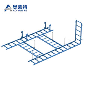
A cable ladder tray is an open cable-support structure consisting mainly of two longitudinal side rails connected by transverse rungs. Cables rest across these rungs while the side rails provide longitudinal structural strength.
The general concept is part of the wider family of cable tray systems used to support insulated electrical, control, and communication cables. Wikipedia’s cable tray overview describes ladder trays as systems in which cables are supported by transverse bars at regular intervals, commonly around 100 to 300 mm. That range is useful for understanding the basic structure, but it should not be treated as a universal engineering specification. Actual rung spacing must match the cable type, tray design, manufacturer data, project requirements, and applicable technical rules.
The open construction is one of the defining characteristics of a cable ladder tray. Unlike a solid-bottom tray, cables are not continuously supported across their entire length. Instead, the rungs provide periodic support while leaving much of the cable surface exposed to surrounding air.
This configuration can make visual inspection, cable identification, modification, and heat dissipation easier. It is particularly useful where relatively large cable routes need organized structural support without completely enclosing the cables.
How Does a Cable Ladder Tray Work?
The easiest mistake to make is to think of the tray as an isolated product. In reality, a cable ladder tray is one part of a structural system.
Cable weight is transferred first to the rungs, then to the side rails, then through hangers, brackets, crossbeams, frames, or other supports into the building or supporting structure. Joints transfer forces between tray sections, while bends, tees, reducers, and vertical transitions change the geometry of the route.
This means system performance is controlled by the interaction of several components.
For example, increasing the strength of the tray section does not solve a weak support connection. Reducing support spacing can improve structural behavior, but additional supports must still be correctly anchored. A long straight run may perform differently from a route with several fittings, vertical transitions, or cable concentrations.
Ventilation is another important characteristic. Because a cable ladder tray leaves large open areas between the rungs, air can circulate around the installed cables more freely than in a fully enclosed tray. This can support thermal management, although actual allowable cable loading and electrical current capacity should always be determined from cable specifications and applicable design requirements rather than assumed from tray geometry alone.
The open construction also makes cable additions and inspections more practical. Maintenance personnel can usually see cable condition and routing without first removing large sections of tray enclosure.
Main Cable Ladder Tray Types and Materials
There is no single material that is automatically best for every cable ladder tray installation. The correct choice depends on structural demand, environmental exposure, installation constraints, electrical considerations, maintenance expectations, and the required service conditions.
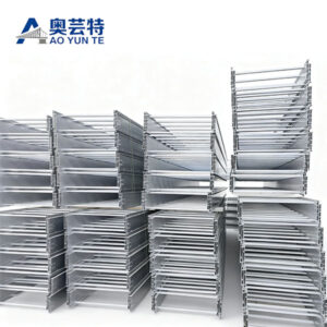
The current ladder cable tray range includes configurations based on different materials, surface treatments, and structural designs, illustrating how ladder systems can be adapted to different engineering requirements.
Galvanized steel is commonly considered where structural strength and general corrosion protection are both important. The zinc-based protective layer helps isolate the underlying steel from normal environmental exposure. The suitability of a particular galvanized finish, however, depends on the actual exposure conditions and fabrication process.
Stainless steel becomes relevant where corrosion resistance and durability take greater priority. The grade should still be selected according to the chemicals, humidity, cleaning processes, temperature, and other environmental factors present at the installation.
Aluminum offers a useful combination of relatively low structural weight, corrosion resistance, and practical handling. It can be particularly valuable where reducing the dead load placed on supporting structures is important.
FRP, or fiberglass-reinforced plastic, provides a different performance profile. It is non-metallic and is often considered where corrosion resistance, electrical insulation characteristics, or reduced metal content are important. Its mechanical and thermal behavior differs from steel, so metal-tray assumptions should not automatically be transferred to an FRP installation.
Powder-coated systems add a protective and decorative surface layer to a metal substrate. Their suitability depends on coating quality, environmental exposure, handling during installation, and whether cutting or modification affects the protective surface.
Long-span and reinforced ladder configurations address structural requirements rather than simply material choice. They use changes in rail geometry, section depth, reinforcement, or overall construction to support longer distances between structural support points where the approved design permits.
Matching Materials to Operating Conditions
A more useful approach is to start with the environment instead of starting with the material name.
If corrosion is the main concern, identify the actual source of exposure. Humidity, chemical vapors, washdown processes, airborne contaminants, condensation, and outdoor exposure create different conditions. A material that performs well in one environment may not provide the same results in another.
If structural weight is critical, compare not only tray mass but also the required support structure. A lighter tray may reduce the demand placed on brackets and overhead framing, but the complete support arrangement still has to meet the required load condition.
If electrical continuity or bonding is required, the properties of joints, connectors, fittings, and surface treatments become part of the design. A cable ladder tray should therefore never be selected solely from a material label.
How to Select the Right Cable Ladder Tray
A reliable selection process starts with the cables rather than the tray.
Begin by identifying what the system must carry. Record cable type, outside diameter, quantity, approximate weight per unit length, bend requirements, grouping restrictions, and the likelihood of future additions.
Next, examine the route. A short run with frequent structural supports creates different requirements from a long route crossing open equipment areas. Vertical sections, changes of direction, tees, reducers, and elevation changes should be considered before determining the final tray configuration.
The installation environment comes next. Corrosion, temperature, dust, moisture, vibration, mechanical exposure, cleaning methods, and maintenance access can all influence material and finish selection.
Finally, examine how the system is expected to change over time. A cable ladder tray that is almost full when installed leaves little flexibility for future circuits. Oversizing without engineering justification is also not automatically better because larger trays affect support loads, installation space, fittings, and structural coordination.
A balanced design reserves practical expansion space while keeping the system organized and structurally efficient.
A Four-Layer Selection Method
A practical way to evaluate a cable ladder tray is to separate the decision into four layers.
The first is the cable layer. Ask what cables must be supported, how heavy they are, how they bend, how they need to be separated, and whether future additions are expected.
The second is the structural layer. Review tray span, support spacing, side-rail strength, rung design, fittings, connections, concentrated loads, and the capacity of the supporting structure.
The third is the environmental layer. Consider corrosion, temperature, moisture, contaminants, vibration, outdoor exposure, and any special operating conditions.
The fourth is the lifecycle layer. Consider inspection access, future cable changes, cleaning, repair, expansion, and whether replacement of individual components will be practical.
This four-layer method prevents a common problem: choosing a cable ladder tray that solves one requirement while creating another problem elsewhere in the system.
Cable Load, Span and Support Spacing
Load and span should always be evaluated together.
A cable ladder tray carries its own weight plus the weight of cables, fittings, accessories, and other approved loads. As the distance between supports increases, structural demand on the tray generally increases. The side rails must resist bending while the rungs transfer cable load into those rails.
For this reason, support spacing cannot be selected independently of the tray model.
Manufacturer load information should be reviewed for the actual tray configuration, material, rail depth, section geometry, support condition, and intended span. It is not good practice to take a load value from one tray design and apply it to another simply because both products have similar widths.
Cable distribution also matters. A uniformly distributed load behaves differently from a heavy concentration of cables at one location. Transitions and fittings may introduce additional structural considerations because load paths change around bends, junctions, and vertical sections.
The same principle applies to field modifications. Adding cables after commissioning changes the loading condition. If enough additions are made over time, the system can move beyond the assumptions used during the original design.
For a more complete understanding of this relationship, the site’s existing cable tray support design guide examines how support positioning, load distribution, anchoring, and structural planning affect the stability of a cable tray system.
The key engineering lesson is simple: tray capacity is not only a property of the metal or composite section. It is a property of the installed system.
Cable Ladder Tray Sizing: Width, Height and Rung Spacing
Width is usually the first dimension people consider, but it should not be the only one.
The required width depends on cable quantity, cable diameters, separation requirements, installation method, and planned spare capacity. Cables should not simply be compressed into the smallest possible tray. A crowded route is harder to inspect, organize, modify, and maintain.
Side-rail height influences containment and structural behavior. Deeper rails may also change the stiffness of the tray, but dimensions alone do not establish load capacity. Section geometry, material thickness, forming method, connections, and span all contribute.
Rung spacing should be appropriate for the cables being supported. Large, stiff cables may behave differently from smaller or more flexible cables. Designers should make sure cables are adequately supported and that individual cables do not sag between rungs in a way that creates unwanted mechanical stress.
Bend radius is another important sizing consideration. A tray may have sufficient straight-run width but still be unsuitable if bends or vertical transitions force cables into tighter curvature than permitted.
A useful sizing review therefore asks four questions:
| Design factor | What should be checked | Why it matters |
|---|---|---|
| Cable quantity | Current cable count and planned additions | Prevents overcrowding and improves future flexibility |
| Cable dimensions | Outside diameter, grouping and separation | Determines usable tray space |
| Cable weight | Distributed and concentrated load | Influences tray and support design |
| Route geometry | Bends, tees, reducers and vertical transitions | Affects cable bending and structural layout |
| Support conditions | Span, bracket type and structural attachment | Directly affects tray performance |
| Environment | Corrosion, moisture, temperature and contaminants | Influences material and surface treatment |
| Maintenance access | Inspection and future cable modification | Improves lifecycle usability |
This table highlights why cable ladder tray sizing should be treated as a multidimensional decision rather than a simple width calculation.
Cable Ladder Tray vs Other Cable Tray Types

A cable ladder tray is not automatically superior to other tray designs. Each configuration solves a different cable-management problem.
Compared with a perforated tray, a ladder design has a much more open supporting surface. This generally improves access and ventilation, while a perforated bottom provides more continuous support for smaller cables.
A solid-bottom tray provides a more enclosed supporting surface and greater separation from the surroundings. This can be useful where additional physical protection or containment is important, but the closed base reduces direct airflow around the cable bundle.
Wire-mesh trays are relatively open and flexible for routing lighter cable systems. Their geometry and load behavior differ significantly from heavier ladder systems, so the two should not be treated as interchangeable.
The selection therefore depends on the priority of the installation.
If the main concerns are structural support for larger cable runs, ventilation, inspection access, and ease of future modification, a cable ladder tray may be a strong candidate. If small-cable support, environmental shielding, or full-bottom containment is the priority, another tray configuration may be more appropriate.
A good cable management design begins by identifying the problem that needs to be solved rather than selecting a tray type first.
Installation and Support Design
Good cable ladder tray performance begins before the first tray section is installed.
The route should be coordinated with structural elements, equipment, access zones, ventilation systems, piping, lighting, and other services. Enough space should remain around the tray for cable installation and future maintenance.
Supports should be positioned according to the tray system requirements and the structural conditions of the project. Bends, tees, risers, reducers, and other fittings may require additional attention because they change both cable direction and structural load paths.
Connections between tray sections should maintain alignment and should be assembled using the specified hardware. Uncontrolled field drilling, cutting, or welding can alter protective finishes and structural behavior.
Where metallic systems require electrical bonding or grounding, continuity across joints and fittings must be handled according to applicable project requirements. The presence of a metal tray should never be assumed to provide an adequate electrical path without verification.
Thermal movement may also matter on long runs or where significant temperature changes occur. Expansion provisions should be considered where required by the tray design and installation conditions.
Cable fastening is especially important on vertical or inclined sections. The tray supports the route, but individual cables may require additional restraint to prevent movement or excessive mechanical stress.
The most reliable installations are those in which the tray, supports, cables, fittings, and surrounding structure have been designed as one coordinated system.
Where Is Cable Ladder Tray Commonly Used?
Cable ladder tray systems are widely applicable where cables need open, accessible, and structurally organized routing.
Industrial production facilities often use ladder systems for power, control, and automation cables that travel between equipment areas. The open design simplifies visual inspection and makes later cable additions easier when production layouts change.
Power distribution environments can use ladder trays where relatively large cables need reliable structural support over coordinated routes. In these installations, load distribution, bend radius, cable separation, and support design become particularly important.
Communication and data infrastructure may also use ladder-style systems, although cable size, tray dimensions, loading, and routing density can differ from heavy electrical installations.
Equipment rooms and utility corridors benefit from the clear organization provided by ladder systems. Multiple cable groups can be arranged in defined routes while remaining accessible for inspection and maintenance.
Infrastructure and renewable-energy installations may involve long cable routes, outdoor exposure, or complex support conditions. In these cases, material selection and corrosion resistance may be just as important as tray dimensions.
The important point is that application names alone should not determine tray selection. Two facilities within the same industry can have very different cable loads, environmental exposure, structural constraints, and maintenance requirements.
Common Cable Ladder Tray Selection Mistakes
One of the most common mistakes is choosing a tray based only on width.
Width tells you whether cables may physically fit, but it says little about structural performance, environmental suitability, rung support, span, or future loading.
Another mistake is treating support spacing as a construction detail that can be decided after tray selection. Support spacing directly affects structural demand and should be considered during system design.
Material substitution can also create problems. Steel, stainless steel, aluminum, FRP, and coated products have different mechanical, corrosion, thermal, and electrical characteristics. Replacing one with another without reviewing the complete design can change system behavior.
Fittings are sometimes overlooked during early planning. Straight tray sections may be easy to specify, but real routes require bends, tees, reducers, risers, joints, and support transitions. These components need enough installation space and must remain compatible with cable bending requirements.
Another frequent issue is uncontrolled future expansion. A tray can begin with a reasonable cable load and gradually become overloaded as new circuits are added. Maintaining accurate cable records and reviewing system loading before major additions helps preserve the assumptions of the original design.
Finally, visual appearance should not be used as evidence of structural capacity. Two cable ladder tray systems can look nearly identical while having very different rail sections, material thicknesses, connection details, and approved load performance.
Inspection, Maintenance and Lifecycle Performance
Cable ladder trays are relatively accessible, but accessibility only has value when inspections are actually performed.
Routine reviews should look for tray deformation, loose connections, damaged supports, corrosion, coating damage, displaced cables, debris accumulation, and changes in cable loading.
Support points deserve particular attention because they transfer the tray load into the surrounding structure. A tray section may appear undamaged even when a bracket, hanger, anchor, or connection has begun to loosen.
Cable condition should also be examined where possible. Sharp edges, damaged fittings, excessive cable movement, tight bends, or poorly positioned restraints can create mechanical stress over time.
When new cables are added, the change should be treated as an engineering modification rather than merely a maintenance task. Additional cable weight affects tray loading, and new cable groups may change thermal or separation requirements.
Good lifecycle management therefore combines physical inspection with documentation. Knowing what was originally installed, what loading assumptions were used, and what modifications have been made provides a much clearer basis for future decisions.
Final Selection Checklist

Before finalizing a cable ladder tray specification, compare the proposed tray configuration with the actual cable schedule and route layout. Check that the selected width and rail height provide enough usable space for the planned cables, including reasonable allowance for future additions, and confirm that bends, tees, reducers, and vertical sections suit the required cable bending conditions.
Next, verify the structural details against the intended installation. The tray model, support spacing, brackets, hangers, joints, and fittings should all correspond to the expected distributed and concentrated loads. Any areas where cables accumulate, change direction, or transition vertically deserve additional attention because these locations can place different demands on the tray and support system.
Finally, review practical installation conditions before approval. Confirm material compatibility with the operating environment, accessibility for inspection and maintenance, compatibility between tray sections and accessories, and any applicable bonding or grounding provisions. This final review is intended to catch specification gaps before installation begins.
Conclusion
Choosing a cable ladder tray is not simply a matter of selecting a width, material, and finish.
A reliable system begins with the cables themselves and then works outward to tray dimensions, structural capacity, support spacing, route geometry, environmental exposure, fittings, maintenance access, and future expansion.
The open ladder configuration offers clear advantages where ventilation, accessibility, organized routing, and structural support are important. Those advantages are strongest when the tray is selected as part of a complete cable management system rather than treated as an isolated component.
For 2026 projects, the most practical approach is to evaluate cable, structural, environmental, and lifecycle requirements together. That method reduces the risk of oversimplified selection and produces a cable ladder tray system that is easier to install, inspect, modify, and maintain throughout its working life.
FAQ
What is a cable ladder tray used for?
A cable ladder tray supports and organizes electrical, control, communication, and other approved cables along planned routes. Its open rung structure provides regular cable support while allowing ventilation, visual inspection, maintenance access, and relatively straightforward future cable additions.
How do I choose the right cable ladder tray size?
Start with cable quantity, outside diameter, weight, separation requirements, bend radius, and realistic future expansion. Then evaluate tray width, rail height, rung spacing, route geometry, support span, and load capacity together instead of selecting the tray solely according to cable width.
How much weight can a cable ladder tray support?
There is no universal load value for every cable ladder tray. Capacity depends on material, rail geometry, thickness, rung design, span, connection method, and support conditions. Always use load information for the exact tray configuration and verify that the supporting structure is suitable.
Which material is best for a cable ladder tray?
The best material depends on the operating environment. Galvanized steel, stainless steel, aluminum, FRP, and coated systems offer different combinations of strength, corrosion resistance, weight, and electrical characteristics. Material selection should follow actual exposure and structural requirements.
What is the difference between cable ladder tray and perforated cable tray?
A cable ladder tray supports cables on spaced rungs and leaves most of the cable surface open, which favors ventilation and access. A perforated tray provides a more continuous supporting base with ventilation openings, which can be useful for smaller cables requiring broader bottom support.