-
Xinzhen Town Industrial Zone, Wen'an County, Langfang City, Hebei Province

Electric Cable Tray Essentials for Power and Control Wiring
Recent News
View Products
Contact Us
Table of Contents
Introduction

An electric cable tray is much more than a pathway that keeps electrical cables organized. In modern power distribution, control, automation, and communication systems, the tray becomes part of the physical infrastructure that determines how cables are supported, separated, ventilated, inspected, and expanded over time.
This becomes especially important when one facility contains several different cable functions. Large power cables may share the general routing area with control circuits, instrumentation cables, communication lines, and equipment connections. These cables do not necessarily require the same tray structure, support conditions, or routing strategy.
A reliable electric cable tray design therefore begins with the cables rather than the tray itself. Cable diameter, weight, electrical function, bending requirements, grouping, environmental exposure, support span, and expected future additions all influence the final system.
Tray type also matters. Ladder, perforated, solid-bottom, wire-mesh, and channel systems provide different balances of structural support, ventilation, physical protection, and accessibility. Material selection adds another layer because steel, stainless steel, aluminum, and composite systems respond differently to load and environmental exposure.
This guide explains how to evaluate an electric cable tray as part of a complete electrical routing system, with particular attention to power and control wiring, structural capacity, thermal conditions, fittings, installation, and long-term expansion.
What Is an Electric Cable Tray?
An electric cable tray is a structural system used to support and route insulated electrical cables through a defined pathway.
It can carry power, control, instrumentation, communication, and other suitable cable groups depending on the electrical design and applicable installation requirements. The general concept of electrical wiring includes conductors, cables, and associated wiring methods used to distribute electrical power and signals, while cable tray systems provide one of the mechanical pathways through which suitable cables can be organized.
The word “tray” can be misleading because the structure does not always resemble a conventional solid tray.
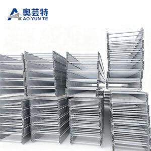
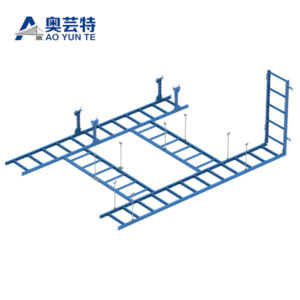
A ladder cable tray uses transverse rungs between two side rails. A perforated system uses a ventilated supporting base. A solid-bottom design provides continuous support, while wire-mesh systems create an open grid structure.
The electric cable tray is also only one part of the completed route.
Bends, tees, reducers, connectors, supports, covers, dividers, and other compatible components allow the tray to pass through real equipment and structural layouts.
This is why tray selection should not be separated from route planning. A suitable straight tray can still become difficult to use if its fittings, support positions, or branch capacities do not match the cable system.
How an Electric Cable Tray Supports Electrical Wiring
The mechanical function of an electric cable tray is based on load transfer.
Cable weight acts on the tray base, rungs, or grid. That load then passes into the side rails or structural sections of the tray before being transferred through brackets, hangers, frames, or other supports into the surrounding structure.
This sequence means that cable tray performance is not determined by the tray section alone.
A strong tray installed on unsuitable supports can still perform poorly. Likewise, appropriate brackets cannot compensate for a tray profile that is not suited to the cable load or intended span.
Cable distribution also influences the load.
A group of cables arranged relatively evenly across the tray creates a different condition from several heavy cables concentrated along one side. Branch points can create local changes because part of the cable load leaves the main route while other cables continue.
Vertical routes create another condition because cable weight can act differently along the direction of the pathway.
The complete cable-support structure should therefore be reviewed as one load path rather than as independent products.
Main Electric Cable Tray Types
Different tray structures exist because electrical cables do not all require the same support conditions.
The main differences relate to how much continuous support the cable receives, how open the route remains, how easily cables can be accessed, and how the tray behaves under structural load.
| Electric cable tray type | Structural design | Main advantage | Main factor to evaluate |
|---|---|---|---|
| Ladder tray | Side rails with transverse rungs | Open support and ventilation | Cable weight, rung spacing and span |
| Perforated tray | Continuous base with openings | Broad support with airflow | Cable arrangement and thermal conditions |
| Solid-bottom tray | Continuous closed base | Full bottom support | Heat, drainage and accessibility |
| Wire-mesh tray | Open welded grid | Visibility and flexible routing | Cable load and support interval |
| Channel tray | Narrow supporting pathway | Efficient branch routing | Cable quantity and route dimensions |
| Long-span tray | Reinforced structural profile | Wider support intervals | Load, stiffness and structural attachment |
The cable tray systems used in electrical routing can therefore vary significantly even when they perform the same general function of supporting cables.
A ladder tray is often appropriate where larger cable groups benefit from open support and inspection access. Perforated trays provide more continuous bottom contact, which can suit smaller cable groups that need broader support.
Solid-bottom trays provide a fully supporting base but create different airflow and drainage conditions. Wire-mesh systems offer a highly open pathway for suitable lower-load cable groups.
The correct electric cable tray type should follow the cable and route requirements rather than being selected only from familiarity.
Electric Cable Tray for Power Cables

Power cables can place substantial mechanical demands on a tray because individual cables may have large outside diameters and significant weight.
The first sizing question is therefore not simply whether the cables fit inside the tray.
The tray and its supports must also carry the resulting distributed load.
A wider tray provides more physical cable space, but that additional space can eventually accommodate more weight. Width and structural capacity should therefore be evaluated separately.
Cable bending is another major consideration.
Large power cables can require generous space at horizontal and vertical changes of direction. A tray that provides sufficient straight-run width may still create an unsuitable route if elbows or risers are too compact.
This is why power cable routes should be evaluated from beginning to end.
Main sections, branch fittings, vertical transitions, reducers, equipment connections, and final drops all need appropriate geometry.
Ventilation can also influence tray selection.
An open ladder structure exposes more of the cable surface to surrounding air than a solid-bottom design. However, actual cable thermal performance depends on cable loading, grouping, ambient temperature, electrical current, and the applicable electrical design.
An open electric cable tray can support ventilation, but it should not be treated as a substitute for proper electrical cable calculations.
Electric Cable Tray for Control and Automation Wiring
Control and automation wiring often creates a different tray design problem.
Individual cables may be much smaller than large power cables, but the total quantity can increase rapidly as equipment becomes more connected.
Sensors, actuators, controllers, monitoring devices, communication equipment, and automation systems can introduce many cable routes within a limited area.
Physical organization therefore becomes particularly important.
A tray can remain well below its structural load limit and still become difficult to maintain if cables are installed without a clear routing pattern.
Grouping cables according to destination or function can make branch points easier to understand. Cables that will leave the main route through the same tee can be positioned logically before they reach the fitting.
Separation requirements also need to be considered.
Power, control, communication, and sensitive signal cables may have different routing requirements. Physical space alone does not determine whether they should share one tray.
Depending on the electrical design, separate trays, dividers, different elevations, or other routing methods may be appropriate.
For control and automation systems, the best electric cable tray therefore supports both cable quantity and cable organization.
Choosing the Correct Electric Cable Tray Size
Electric cable tray sizing starts with the cable schedule.
Cable outside diameter, weight, quantity, function, grouping, separation requirements, and expected future additions provide the basic information needed to determine tray dimensions.
Width is usually the first dimension considered.
It defines the lateral space available for cable arrangement. However, nominal width is not always equal to usable cable space because dividers, side rails, fasteners, restraints, and fittings can reduce the area available in practice.
Height also matters.
A deeper tray can provide greater lateral containment and additional volume, but excessive cable layering can make lower circuits difficult to identify and remove.
A tray should therefore not be sized simply by calculating the total cable cross-sectional area and choosing the smallest dimensions that appear to fit.
Real installations contain gaps between round cables, organized groups, branch movements, cable restraints, and working space.
Future capacity should be considered as well, but it should be realistic.
A tray that is dramatically oversized can occupy unnecessary structural space and create the potential for much higher future cable loading.
The right size balances initial cable arrangement, future development, structural capacity, fitting geometry, and maintenance access.
Electric Cable Tray Load and Support Span
Support span directly affects how an electric cable tray behaves under load.
As the distance between structural supports increases, the tray experiences different bending conditions. Side-rail profile, material thickness, tray width, structural geometry, joints, and cable load all influence the result.
This means support spacing should not be selected after the tray has already been finalized.
The available structural attachment points should be understood early.
In a simple corridor, brackets or hangers may be positioned regularly. Around equipment, structural beams, piping, ducts, and maintenance zones, the available support locations may be more restricted.
If the actual support distance is longer than expected, the tray configuration may need to change.
Long-span systems can address some of these situations by using reinforced profiles or deeper structural sections, but the term “long span” does not eliminate the need for load evaluation.
Cable load should also include realistic future additions where expansion is expected.
A tray can remain physically spacious while gradually approaching the structural assumptions used in its original design.
The existing Aoyunte discussion of electrical cable tray systems treats tray type, support, installation, and industrial wiring as connected design factors, which reflects how the installed route actually behaves as a complete system.
Thermal Performance and Cable Ventilation
Heat is an important consideration in electrical cable routing, particularly where significant power cable groups are installed.
Tray structure influences airflow around the cable bundle.
Ladder and wire-mesh systems are highly open. Perforated trays provide ventilation through openings, while solid-bottom systems create a more enclosed condition.
However, more open tray geometry does not automatically guarantee low cable temperature.
Cable density matters.
If many cables are tightly layered together, air movement around individual cables can still be limited even when the tray has large openings.
Electrical loading also matters because heat generation is related to how the cables are operating, not simply to the tray structure.
Ambient temperature, surrounding airflow, covers, cable grouping, and nearby equipment can further influence thermal conditions.
The electric cable tray should therefore support the thermal strategy of the electrical system rather than being treated as the only factor controlling cable temperature.
Where ventilation is a major priority, an open structure may provide practical advantages. Where physical protection is more important, a more enclosed tray can be suitable if thermal requirements are addressed appropriately.
Material Selection for Electric Cable Tray
Tray material influences structural weight, corrosion behavior, fabrication, electrical conductivity, and long-term maintenance.
Steel is widely used because it can provide strong structural performance. Surface treatments can be applied according to the operating environment.
Stainless steel offers different corrosion characteristics and can be considered where moisture or contaminants create more demanding exposure.
Aluminum provides a lower-weight metallic alternative. Reduced tray self-weight can be valuable on overhead routes where the support structure already carries substantial cable loads.
FRP and other composite materials provide non-metallic characteristics and can be useful where corrosion resistance or electrical insulation properties are important.
The environment should be defined before material is selected.
Simply describing an installation as industrial, indoor, or outdoor provides limited technical information.
Humidity, condensation, chemicals, dust, temperature, washdown conditions, sunlight, vibration, and other exposure factors can influence the decision.
Material should also be coordinated with connectors, fittings, brackets, and fasteners.
A highly durable tray combined with less suitable accessories can create localized weak points within the electrical cable route.
Fittings Determine Whether the Route Is Practical
Straight electric cable tray sections are relatively easy to plan. Fittings create most of the geometric complexity.
Horizontal elbows allow the tray to turn on the same level. Vertical bends move cables between elevations. Tees create branches, while crosses connect several directions. Reducers allow tray width to decrease as cable quantities change.
Each fitting affects the cable arrangement.
At a bend, cables need enough space to follow the required curvature. At a tee, the cable bundle needs to separate into different destinations. At a reducer, cables need to move into a narrower arrangement without becoming unnecessarily congested.
This makes fittings potential bottlenecks.
A straight tray can retain significant spare width while the main branch fitting has almost no practical room for additional cables.
Future expansion should therefore be reviewed through bends and branch points as well as straight sections.
The external dimensions of fittings also matter.
An elbow occupies more surrounding space than a straight tray of the same width. Nearby structures and other services can interfere with the fitting even when the straight route appears clear.
Good electric cable tray planning considers the most difficult fittings before finalizing the entire pathway.
Cable Separation and Electrical Organization
A cable tray can provide substantial physical space, but not every cable should automatically be placed together.
Different electrical circuits can have different separation, interference, safety, and maintenance requirements.
The appropriate arrangement should follow the electrical design of the project.
Where compatible cable groups can share a tray, organization still matters.
Dividers can create defined zones within a wider tray where appropriate. Separate trays can be used where stronger physical separation is required.
Routing cables by function or destination can also simplify maintenance.
When a technician needs to trace a control circuit, an organized tray is much easier to work with than one containing cables that cross repeatedly without a clear pattern.
Branch points benefit particularly from good organization.
If cables serving one equipment area are already grouped before reaching a tee, they can leave the main tray without crossing several unrelated cable groups.
Electrical organization therefore improves the usability of the tray even when it does not change the tray’s structural capacity.
Electric Cable Tray vs Conduit
Electric cable tray and conduit both provide methods for routing electrical cables, but they solve different problems.
Cable trays create an accessible pathway where several cables can be supported together. Many tray structures allow cables to remain visible and reachable along much of the route.
Conduit encloses conductors or cables inside a tube-like pathway, providing a different level of physical separation from the surrounding environment.
Accessibility is one of the major practical differences.
Where a cable tray remains reachable, additional suitable cables can often be introduced without rebuilding the entire pathway.
Enclosed routing methods can require cables to be pulled through the available internal space.
This does not make one approach universally better.
Equipment connections, exposed local routes, mechanical protection requirements, environmental conditions, cable type, and applicable electrical requirements can favor different methods.
Many electrical systems use several routing approaches together.
The main distribution route may use electric cable tray, while local connections or exposed drops use a different wiring method suited to their specific conditions.
The most effective design uses each method where its characteristics provide the greatest practical advantage.
Outdoor and Harsh-Environment Electric Cable Tray
Outdoor electrical routing introduces conditions that are less significant in many indoor installations.
Rain, condensation, sunlight, temperature cycling, wind, airborne contaminants, and debris can affect the cable tray and its supporting structure.
Material selection becomes particularly important.
Galvanized steel, stainless steel, aluminum, and composite systems provide different environmental performance characteristics.
Drainage also needs consideration.
Open ladder structures allow water to pass through easily, while solid-bottom systems may require a more deliberate drainage strategy.
Covers can provide additional protection from direct environmental exposure, but they also change airflow and increase the surface exposed to wind.
Thermal movement can become important on long outdoor routes because tray materials expand and contract as temperature changes.
Support hardware must also suit the same environment.
Selecting a corrosion-resistant electric cable tray while using poorly matched brackets or fasteners can create an inconsistent system.
Outdoor design should therefore address the complete tray, fittings, covers, supports, anchors, and cable arrangement as one environmental system.
Installation Quality and Electric Cable Tray Performance
A well-designed electric cable tray can still become difficult to use if installation changes the original design assumptions.
Tray sections should remain aligned so cables travel through a smooth pathway.
Connectors and fittings should match the tray system, and supports should be positioned according to the intended load and structural arrangement.
Field cutting and drilling require attention because they can alter protective surfaces or create sharp cable-contact edges.
Working clearance is equally important.
The space occupied by the finished tray is not the same as the space needed to install cables.
Large cables may require room to approach and pass through a bend. Technicians need access to joints, brackets, cable restraints, and branch fittings.
A route installed too close to other infrastructure can be structurally correct while remaining extremely difficult to maintain.
Vertical sections may need additional cable restraint depending on cable type and route conditions.
Installation should therefore preserve both structural reliability and the accessibility that made the tray system useful in the first place.
Planning Electric Cable Tray for Future Expansion
Future cable expansion is one of the main reasons to preserve accessible tray pathways.
However, expansion capacity should not be measured only by unused tray width.
A future cable has to pass through every bend, tee, reducer, vertical transition, and equipment connection along its route.
If one fitting is already congested, spare space on the straight sections provides limited value.
Structural capacity should also be reviewed.
New cables increase load regardless of whether the tray appears visually full.
This means future expansion should include both physical and structural planning.
The location of spare capacity should follow realistic equipment development.
A main distribution route serving areas expected to change regularly may need more expansion capability than a short fixed branch.
Abandoned cables should also be managed.
Inactive cables occupy usable space and add weight. Removing them where appropriate can restore capacity and improve cable identification.
The most scalable electric cable tray is therefore not the largest one. It is the system that preserves usable space and structural capacity where future cables are actually expected to travel.
Common Electric Cable Tray Design Mistakes
One common mistake is selecting tray size before the cable schedule is fully understood.
This can result in a tray that has the correct nominal width but does not accommodate cable grouping, bending, separation, or future branch requirements.
Another mistake is assuming that physical capacity equals structural capacity.
A tray can have substantial empty space while its support system is already carrying a large cable load.
Thermal conditions can also be oversimplified.
An open tray does not automatically solve every heat issue, while a solid-bottom tray is not automatically unsuitable for power cables. Cable loading, grouping, environment, and electrical design all matter.
Support planning is sometimes left too late.
If structural attachment points do not match the required support spacing, installers may need to change the route after other design decisions have already been finalized.
Material selection can also become too generic.
Terms such as outdoor or industrial are not detailed enough to determine corrosion resistance or environmental suitability.
Finally, future expansion is often considered only along the straight route.
Bends, tees, vertical transitions, and structural supports need the same expansion planning.
Inspection and Long-Term Maintenance
Electric cable tray systems remain useful only when changes in their condition and loading are identified over time.
Routine inspection should consider tray alignment, supports, joints, fittings, corrosion, coating condition, cable congestion, restraints, and physical damage.
Supports deserve particular attention because they transfer the full system load into the surrounding structure.
Cable arrangement should also be reviewed as new circuits are added.
An initially organized tray can gradually become difficult to maintain if new cables are installed without following the original routing logic.
Branch fittings can become congested earlier than straight tray sections.
Removing abandoned cables can improve both physical capacity and visibility.
The operating environment may also change.
New equipment can introduce additional heat, vibration, contaminants, or access restrictions that were not present during the original design.
Maintenance should therefore evaluate whether the electric cable tray still matches its current cable load and operating conditions rather than only checking whether the tray itself is visibly damaged.
Building a Better Electric Cable Tray Routing Strategy

A strong cable routing strategy usually has a clear hierarchy.
Main trays carry larger groups across primary electrical routes. Branch trays separate those groups according to destination, while smaller pathways serve individual equipment areas.
This structure allows tray dimensions to change as cable quantities change.
It can also make cable identification easier because the physical route reflects the logical layout of the electrical system.
Fittings should be placed where cable groups naturally separate.
Supports can then be positioned according to the actual loading and route geometry.
Material can vary where environmental conditions change, provided transitions are technically compatible.
Future expansion can follow the same hierarchy.
New cables enter established main routes and leave through planned branches rather than creating improvised pathways around existing systems.
An electric cable tray becomes much easier to operate when the physical infrastructure makes the cable network understandable.
Conclusion
An electric cable tray is a structural part of the electrical wiring system, not simply a container for cables.
Its performance depends on how well tray type, dimensions, material, cable load, support span, fittings, thermal conditions, separation, installation access, and future expansion are coordinated.
Power cables may prioritize structural support and bend geometry, while control and automation routes can place greater emphasis on organization and accessibility. Different tray structures and materials address these requirements in different ways.
The most reliable design begins with the cable system and works outward.
When cable behavior, route geometry, environmental conditions, and structural support are understood before the tray is selected, the resulting system is easier to install and more adaptable to future electrical changes.
A well-designed electric cable tray therefore supports more than cables. It supports the long-term organization and flexibility of the electrical infrastructure itself.
FAQ
What is an electric cable tray used for?
An electric cable tray supports and organizes suitable power, control, instrumentation, communication, and other electrical cables along a defined route. It provides mechanical support while helping maintain accessible wiring pathways through straight sections, bends, branches, equipment areas, and future system expansions.
How do I choose the right electric cable tray?
Start with cable diameter, weight, function, grouping, bend requirements, and future additions. Then evaluate tray type, width, height, material, support span, fittings, environmental exposure, thermal conditions, and maintenance access. Selection should follow the complete cable route rather than one dimension.
Which electric cable tray is suitable for power cables?
Ladder and other structurally rated tray systems can be suitable for power cables when their load capacity, dimensions, rung or base support, fittings, support spacing, and material match the cable requirements. Cable weight, bending radius, grouping, ventilation, and electrical design should all be checked.
Can power and control cables use the same electric cable tray?
They may share a cable tray only where the electrical design and applicable requirements permit the arrangement. Cable separation, interference, grouping, and maintenance needs should be considered. Dividers, separate tray sections, or independent routes can be used where stronger separation is necessary.
How should an electric cable tray be planned for future expansion?
Future capacity should exist through the whole pathway, including straight trays, bends, tees, reducers, vertical sections, and supports. Additional cable weight should remain within structural limits, while realistic spare routing space and organized branch layouts make future additions easier to manage.