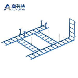
-
Xinzhen Town Industrial Zone, Wen'an County, Langfang City, Hebei Province

How to Choose Cable Tray Sizes for Reliable Cable Routing
Recent News
View Products
Contact Us
Table of Contents
Introduction

Choosing cable tray sizes is not simply a matter of finding a tray wide enough to hold the cables in front of you. A tray can appear spacious during the initial installation and still become difficult to maintain after additional circuits are introduced. Conversely, specifying an unnecessarily large tray can increase structural demands, occupy valuable routing space, and make fittings and supports more complicated than the installation requires.
A more reliable sizing decision considers the cable bundle, tray type, usable internal space, cable weight, support arrangement, bend geometry, environmental conditions, and realistic future expansion at the same time. These factors are connected. Changing the tray width can change the load carried by each support, while changing the side height can influence containment and the physical space required around bends and fittings.
This guide explains how to evaluate cable tray sizes from an engineering and practical installation perspective. Rather than presenting one universal size chart, it focuses on why different dimensions exist and how you can determine which combination of width, height, length, and structural configuration actually fits a cable route.
What Do Cable Tray Sizes Actually Mean?
When cable tray sizes are described, width is usually the first dimension people notice. It represents the horizontal space available for arranging cables, but it is only one part of the tray geometry.
Height, sometimes described in relation to the side rail or side wall, determines how much vertical containment the tray provides. Length describes the individual tray section rather than the total cable route. Depending on the tray design, other dimensions such as rung spacing, perforation pattern, rail profile, wire spacing, material thickness, and fitting radius can also affect how much usable space the completed system provides.
This distinction matters because nominal dimensions and usable cable space are not always identical. Connectors, fasteners, cable separation arrangements, side walls, covers, and installation clearances can reduce the space that is practically available.
The broader concept of cable tray systems includes ladder, ventilated, solid-bottom, wire-mesh, and other structures. Their geometries differ because each structure supports and contains cables differently.
For this reason, a 300 mm wide ladder tray and a 300 mm wide enclosed tray should not automatically be treated as equivalent solutions. Their cable support surfaces, airflow, fittings, loading characteristics, and maintenance access may be different even when the nominal width is the same.
Why Cable Quantity Alone Is Not Enough for Sizing
Counting cables is a useful starting point, but cable quantity by itself tells you very little about the size of tray required.
Ten small control cables can occupy less space than two large power cables. Cables with similar outside diameters may also differ considerably in weight, flexibility, minimum bending radius, separation requirements, and heat generation. The characteristics of the actual cable schedule therefore matter more than the number of individual cables.
Before evaluating cable tray sizes, the cable schedule should identify the outside diameter and approximate weight of each cable group. It should also distinguish between cables that can be routed together and those that need physical separation or different routing conditions.
You should then consider how the cables will actually sit in the tray. A theoretical area calculation can be misleading if it assumes that round cables will fill every available space efficiently. Real installations include gaps between cables, natural irregularities in cable placement, restraints, dividers, and space required for installation work.
This is one reason practical cable tray sizing should combine dimensional calculations with an understanding of how technicians will install, inspect, remove, and add cables over time.
How to Choose the Correct Cable Tray Width
Width is primarily determined by the lateral space needed for the planned cable arrangement.
Instead of asking, “What is the standard cable tray width?” a more useful question is, “How much usable width does this particular cable group require under the intended installation conditions?”
Start with the installed cable arrangement rather than the outside dimensions of the tray. Consider whether cables will be installed in a single layer, grouped by function, separated by dividers, or arranged according to specific project requirements. The resulting cable layout provides a more realistic indication of required tray width.
Future capacity also deserves consideration, but spare space should be intentional rather than arbitrary. Designing a tray around an imagined maximum expansion can lead to an oversized support system, while leaving no expansion room can make relatively minor system changes difficult.
A better approach is to base spare capacity on the expected development of the installation. A fixed production line, for example, may have different expansion expectations from a modular facility where equipment and cable routes are regularly modified.
Aoyunte’s current stainless steel cable tray specifications list regular widths from 50 mm to 1200 mm and regular heights from 50 mm to 200 mm. These figures demonstrate the breadth of configurations available within one product type, but they should not be interpreted as universal dimensions for every tray structure or every application.
The correct width is therefore not the largest option available. It is the width that accommodates the planned cable arrangement while remaining compatible with structural, routing, and maintenance requirements.
How Tray Height Affects Cable Management
Height receives less attention than width, yet it can significantly affect the way a tray performs in an actual installation.
Higher side walls can provide greater lateral containment and can be useful where cable bundles are relatively deep. Side-rail geometry may also contribute to the structural stiffness of certain tray designs. However, increasing tray height does not automatically mean that more cables should be stacked into the available volume.
Cable placement still needs to respect the installation requirements of the cables themselves. Excessive layering can make lower cables difficult to inspect and can complicate replacement or maintenance. In applications where cable temperature is important, dense stacking may also change the thermal conditions within the bundle.
Height becomes especially important where covers are installed. The designer needs to consider not only whether the cables fit below the top edge but whether sufficient clearance remains between the installed cable bundle and the cover.
Vertical clearance around the tray should also be reviewed. A dimension that fits on a drawing may become impractical if surrounding equipment, structural beams, piping, or other building services leave insufficient room to install cables from above.
The best tray height therefore balances containment, structural requirements, cable arrangement, access, and the available installation envelope.
Cable Tray Sizes Vary by Tray Type
Tray dimensions cannot be separated from tray structure. Ladder, perforated, solid-bottom, and wire-mesh trays manage cables in different ways, so the same nominal dimensions can produce different practical results.
Ladder trays support cables on transverse rungs and leave large areas open. Their sizing decisions often place greater emphasis on cable diameter, cable weight, rung spacing, side-rail strength, and support span.
Perforated trays provide a broader supporting surface with openings for airflow and drainage. They can be useful where cables benefit from more continuous bottom support while still requiring some ventilation.
Solid-bottom trays provide continuous support and greater physical separation from the surrounding environment. The available internal dimensions may need to account more carefully for cable layering, ventilation conditions, covers, and cable entry or exit points.
Wire-mesh trays have an open grid structure and can provide flexible routing for appropriate cable groups. Their load characteristics, support requirements, and usable geometry differ from those of heavier steel ladder systems.
The table below shows how sizing priorities change according to tray structure.
| Cable tray type | Main sizing concern | Additional factor to evaluate | Typical design priority |
|---|---|---|---|
| Ladder tray | Width, rail height and cable weight | Rung spacing and support span | Open support for larger cable routes |
| Perforated tray | Usable width and cable arrangement | Ventilation and bottom support | Balanced support and airflow |
| Solid-bottom tray | Internal width and depth | Cover clearance and thermal conditions | Continuous support and protection |
| Wire-mesh tray | Width, depth and cable bundle size | Grid strength and support interval | Flexible routing and accessibility |
The table is not intended to assign one tray type to every application. Its purpose is to show why cable tray sizes should always be interpreted in the context of tray design.
Cable Weight Changes the Meaning of Tray Size

Physical space is only half of the sizing problem. The tray must also support the installed load.
Two cable routes can occupy exactly the same width while creating very different structural demands. A tray filled with lightweight communication cables may impose a much lower distributed load than a tray of the same size carrying large power cables.
The total design load can include the tray itself, installed cables, fittings, accessories, covers where applicable, and other loads permitted by the system design. Cable additions made later can also change the original load condition.
This is particularly important when wider trays are considered. Increasing width creates more physical room for cables, but that additional capacity can result in more cable weight being placed between the same supports. Tray width should therefore never be increased without considering the corresponding structural consequences.
Support span is closely related to this issue. A tray that performs adequately at one support interval may behave differently when the span is increased. Side-rail profile, material, thickness, joint design, and support position all influence the installed behavior.
Aoyunte’s existing cable tray support design guide discusses the relationship between tray loading, support positioning, anchoring, and structural planning. Treating these elements as one system is more reliable than sizing the tray first and deciding where to support it later.
Support Span Should Be Considered Before Finalizing Size
It is tempting to select cable tray sizes first and leave brackets and hangers to the installation stage. That order can create problems.
Support availability may be limited by the surrounding structure. Columns, beams, equipment, ceiling systems, service corridors, and restricted access areas can determine where supports can realistically be placed. If the intended tray configuration requires closer supports than the route allows, the problem should be identified during design rather than after installation begins.
Longer spans generally increase structural demand. A deeper or more structurally developed side rail may be necessary, but the exact relationship should come from the load information for the selected tray system rather than a general assumption based on visual size.
Joints also deserve attention. Tray section length and support location should be coordinated so that connections are positioned according to the system design. Treating every point along a tray run as structurally identical can overlook the effect of joints, fittings, and changes in direction.
The most useful sizing drawings therefore show more than width and height. They show tray size together with support positions, fittings, route elevations, and major cable concentrations.
Bends and Fittings Can Determine the Real Space Requirement
Straight sections are usually the easiest part of a cable tray route to size. Fittings are where dimensional problems often appear.
Horizontal bends need enough radius to allow cables to change direction without being forced into unsuitable curvature. Vertical bends introduce similar considerations when cables rise or fall between levels. Tees and crosses bring several cable groups into the same routing area, while reducers transition between different cable tray sizes.
A tray may therefore fit comfortably along a straight corridor but require considerably more surrounding space at a bend or junction.
This is why route planning should not be based only on the rectangular footprint of the straight tray. The design needs to consider the full spatial envelope of fittings, connectors, support hardware, cable bending, and installation access.
Cable size plays a major role here. Large or relatively stiff cables usually require more generous routing geometry than smaller flexible cables. If the tray is sized only from straight-run cable capacity, the selected system may become difficult to install at direction changes.
In practice, checking the most constrained bend or junction before finalizing the straight-run size can reveal problems much earlier in the design process.
How Much Spare Capacity Should a Cable Tray Have?
Future expansion is a legitimate design consideration, but there is no meaningful universal percentage that works for every installation.
The amount of spare capacity should reflect how the cable system is expected to develop. If equipment layouts are stable and cable additions are uncommon, a large unused tray area may provide little practical value. Where new circuits, automation equipment, communication systems, or process changes are expected, additional capacity may be much more important.
The important distinction is between planned spare capacity and accidental empty space.
Planned capacity is supported by a realistic expectation of future cable additions and is included when checking tray load, support capacity, fittings, and available route space. Accidental empty space simply results from choosing a tray much larger than required without considering what that larger structure means for the rest of the system.
You should also consider whether future cables can actually reach the tray. Spare space in a straight section has little value if the route’s bends, risers, penetrations, or junctions do not have corresponding capacity.
For this reason, expansion planning should be applied to the entire route rather than only to the widest straight tray sections.
A Practical Method for Selecting Cable Tray Sizes
A useful sizing process begins with three different types of space: cable space, structural space, and working space.
Cable space is the physical area required to arrange the planned cables correctly. This is determined from cable diameters, quantities, grouping, separation, and expected additions.
Structural space is the room required for the tray itself, including side rails, supports, joints, fittings, and any reinforcement necessary for the intended load and span.
Working space is the clearance needed to install and maintain the system. Technicians need access to place cables, inspect connections, add restraints, remove damaged cables, and introduce new circuits later.
These three spaces should be evaluated together because a tray can satisfy one and fail another. A wide tray may provide excellent cable capacity but leave insufficient clearance for installation. A shallow route may fit structurally but force cables into an impractical arrangement. A compact tray may work initially but provide no reasonable access for later maintenance.
Once the three space requirements are understood, compare several tray configurations rather than accepting the first size that appears to fit. Review how each option affects cable arrangement, support loading, bends, fittings, route clearance, and future changes.
This comparative step often produces a better decision than simply moving to the next larger nominal size.
Common Mistakes When Selecting Cable Tray Sizes
One common mistake is sizing the tray from cable area alone. Mathematical area can indicate whether cables theoretically fit, but it does not represent their real arrangement, the spaces between them, installation access, or the geometry required at bends.
Another mistake is treating width as a capacity rating. Width provides space; it does not establish how much cable weight the tray can safely support. Structural capacity must be evaluated separately.
Using the same tray dimensions throughout an entire installation can also create inefficient layouts. Main cable routes, branch routes, equipment drops, and communication sections may have different capacity requirements. Reducers and appropriate fittings can sometimes create a more rational system than maintaining one oversized dimension everywhere.
Designers can also underestimate the space occupied by covers, connectors, dividers, brackets, and fittings. These parts may appear secondary on a product drawing, but they affect both usable tray space and the external installation envelope.
Finally, future capacity should not be treated as permission to keep adding cables indefinitely. Each significant modification can change the load, cable arrangement, thermal conditions, and maintenance accessibility that were assumed when the system was originally designed.
Why Custom Dimensions May Be Necessary
Standardized product ranges are useful because they simplify coordination, production, installation, and replacement. They do not cover every possible routing condition.
Some projects have restricted ceiling zones, unusually large cable bundles, longer structural spans, special cable separation arrangements, or equipment interfaces that make a conventional size impractical. In these situations, a custom tray dimension or structural configuration may provide a more suitable solution.
Customization should still begin with engineering requirements rather than available space alone. Making a tray wider, deeper, longer, or thicker changes more than its appearance. It can affect weight, stiffness, handling, support loading, fittings, installation methods, and connection details.
The most useful custom specification therefore defines the performance requirement first and the dimensions second.
Instead of saying only that a tray must be 800 mm wide, for example, the design information should also establish what cable arrangement it supports, the expected load, the intended support spacing, the required material or surface protection, and how the custom section connects to the rest of the system.
That gives the manufacturer and installation team enough information to evaluate the tray as a functioning component rather than a fabricated channel with unusual dimensions.
Cable Tray Size Changes During System Expansion

Cable tray sizing does not end when installation is completed.
Over the service life of a facility, new equipment may be added, old circuits removed, communication cables rerouted, and electrical loads reorganized. These changes can gradually make the original cable tray sizes less appropriate for the way the system is being used.
Periodic visual inspection can identify congestion, excessive layering, poorly positioned additions, damaged fittings, loose supports, or sections where cables have been introduced without considering the original arrangement.
When a route becomes crowded, installing a larger tray is not always the first solution. Removing abandoned cables, reorganizing cable groups, separating new circuits onto a parallel route, or modifying a local branch may sometimes provide a more practical result.
Where a larger tray is required, the change should include another structural review. More physical capacity can invite more cable loading, so supports and surrounding structures should be checked along with the new tray dimensions.
This lifecycle perspective helps prevent a common situation in which a cable tray remains physically intact but gradually loses the organization and accessibility that made it useful in the first place.
Conclusion
The right cable tray sizes are determined by the cable system and its surroundings, not by a single standard dimension.
Width must provide usable routing space, height must suit the cable arrangement and containment needs, and the complete tray structure must remain compatible with cable weight, support span, fittings, bends, installation clearance, and environmental conditions. Future expansion matters as well, but it should be based on realistic system development rather than simply selecting the largest available tray.
A well-sized cable tray does more than contain cables. It creates an organized route that can be installed correctly, inspected efficiently, modified without unnecessary disruption, and supported reliably throughout its intended service life.
By treating sizing as part of cable management design rather than as a product dimension decision, you can make the tray system easier to coordinate today and more adaptable to the changes that may come later.
FAQ
What are the most common cable tray sizes?
Cable tray sizes vary by tray type and manufacturer rather than following one universal range. Width and height are normally selected according to cable quantity, cable diameter, load, separation, support span, and route conditions. Always verify the dimensions available for the specific tray design being specified.
How do I calculate the cable tray size I need?
Start with the outside diameter, quantity, grouping, and arrangement of the cables rather than cable count alone. Allow practical installation space and planned expansion, then check the resulting tray width and height against load capacity, support spacing, bend requirements, fittings, and available route clearance.
Should I choose a larger cable tray for future expansion?
Some spare capacity is useful when future cable additions are reasonably expected, but simply choosing a much larger tray is not always better. Additional width can increase possible cable loading and structural demand. Expansion space should be planned across straight sections, bends, risers, junctions, and supports as one route.
Does cable tray width determine its load capacity?
No. Width describes available routing space but does not by itself establish structural capacity. Load performance also depends on material, side-rail profile, thickness, tray structure, rung or bottom design, joints, and support span. A wider tray must still be checked against the load data for its exact configuration.
Can different cable tray sizes be used in the same system?
Yes. Different route sections can require different capacities, especially where main runs divide into smaller branches. Proper reducers and compatible fittings can connect appropriately designed sections. Each transition should still account for cable bending, support placement, usable space, and the structural requirements of both tray sizes.